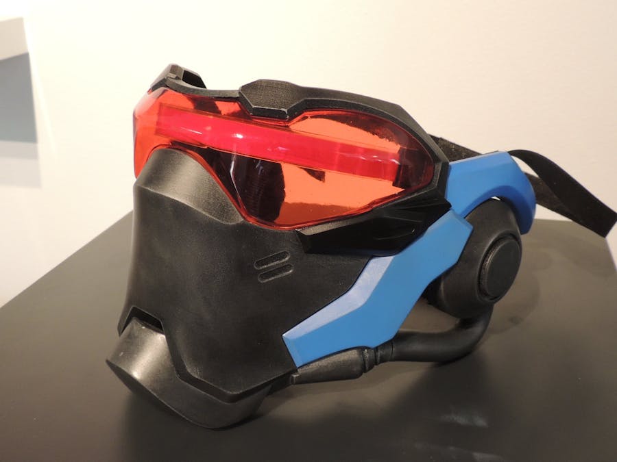
Who doesn't want to be a video game character for Halloween? We designed, printed, and painted this Soldier: 76 (S76) mask just before the spooky holiday, and wanted to share it with you!
One of the most defining features of S76 is their bright red visor, so we included some cool electronics that will let you have a blinking strip of light with the simple touch of a button!
We started by creating a CAD file using dimensions pulled from in game files. The mask was recreated from scratch, and modified slightly to fit the average head. We also made the faceplate separate from the rest of the mask, allowing you to easily hold a conversation or stay hydrated. It's held on with M A G N E T S!
90% of the hard work was in the modeling, so anyone should be able to download our files, print them out, and have yourself a working mask in under a week.
Step 1: Print the ModelsWe used a Formlabs Form2 to print our models, with support enabled. It took a few days, but it was worth it for the extra resolution that the Form2 provided.
These parts could be printed on an FDM printer, but the resolution isn't nearly as good as an SLA part.
The rubber straps that hold the mask on your face should be printed in black Ninjaflex. We printed ours on a Replicator 2, then super glued Velcro to them. You'll need two pairs (four straps total).
Step 2: Sand and Paint Your PartsEven the small layers on our SLA printed parts were visible when painted, so we broke out the sandpaper and got to work! We used 400 and 600 grit sandpaper to get the parts nice and smooth.
After sanding, the parts went into the spray booth and got some nice coats of paint.
We split the mask into different pieces so we could fit the parts onto our 3D printers. The pieces are held together with super glue and M3 bolts that self tap into the plastic. The parts only fit one way, so refer to the following pictures if you're having trouble with assembly!
The ear pucks get glued to the jaw. Apply liberal amounts of super glue, then hold in place 'til dry!
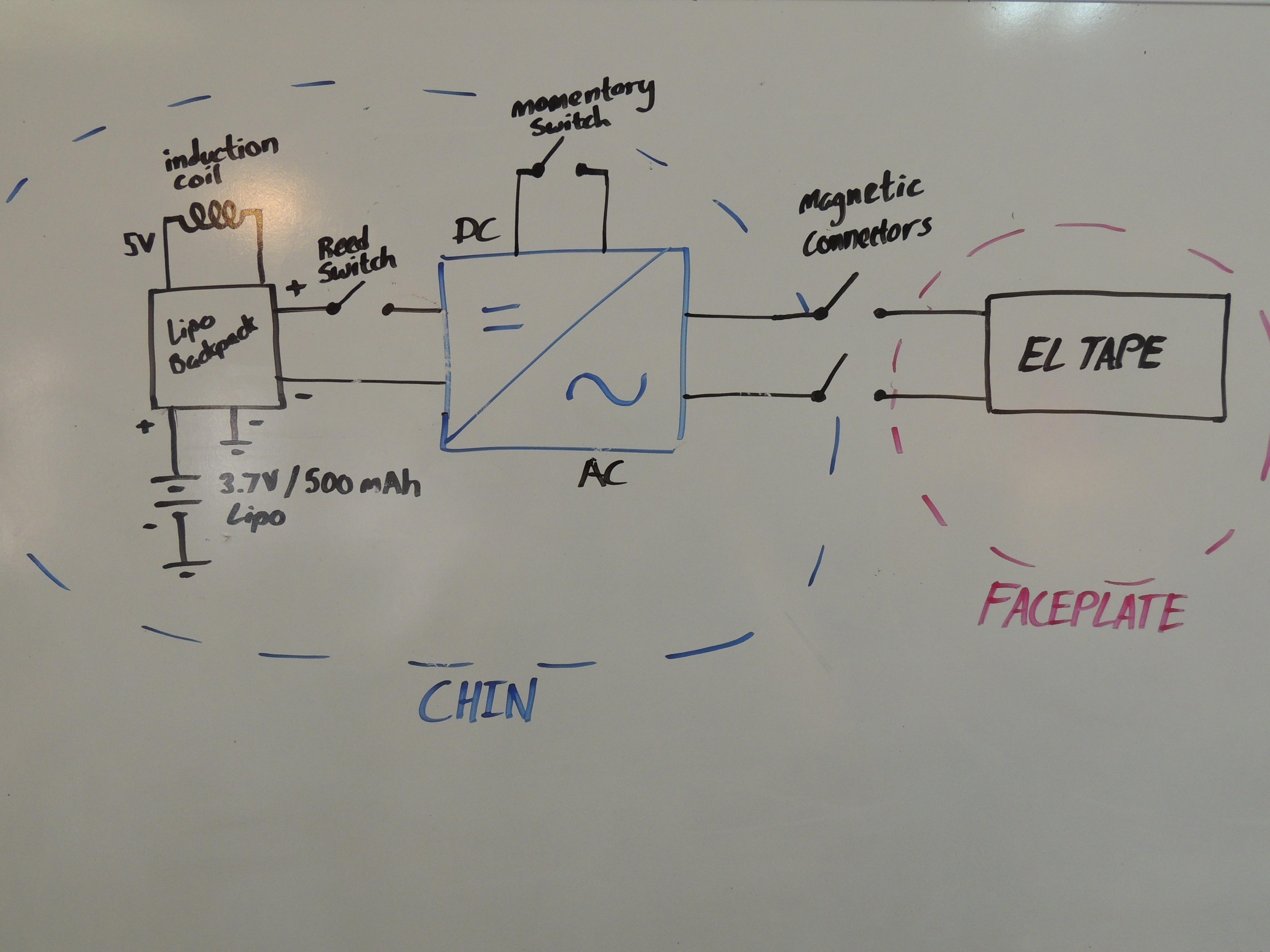
The magnets in the chin are the electrical connections that power the EL tape in the faceplate (while keeping the bulky electronics in the mask).
After inserting the electrical magnet connectors into the chin sockets, make sure that the connection is solid with a multimeter. Those magnets need to be touching!
Insert the normal 3/16" magnets in the other magnet sockets and glue them in place. The single magnet on the left cheek will eventually activate the reed switch, so don't forget that one!
Step 4: Vac forming the VisorHow are we going to get that nice red visor that S76 has? We'll vacuum form it, of course!
Start with printing the visor buck and the visor stand. Since this is going to have hot plastic pressed against it, it's probably best to print this with a high-temp material. We used Formlabs resin as the buck, and ABS as the visor stand.
Once you've glued your buck to your stand, the part can be vac formed.
We need a nice red color for our visors, so we used a dye bath to get the desired hue. You'll need red iDye Poly, a bath of water heated to 60 C, and a bath of ice water.
Soak the visors in the dye mixture for four minutes, then remove and immediately put the visors into ice water, wiping off any surface dye. The ice water helps "freeze" the dye into place, so don't skip that step! Repeat the above steps until you have a nice deep red color.
Next, coat the edges of the visor in a small amount of super glue, and press the visor into place.
We saved the best (And most difficult) for last! These helmets look great without any electronics, but some lights can really send your costume over the edge. We use a lipo battery, EL inverter, and red EL tape to bring this helmet to life.
- Pick up all the electronics from the links provided. If you use different reed switches or EL inverters, the parts may not fit!
- Remove any batteries, and open the EL inverter by removing the single screw underneath the belt clip.
- Pull the PCB out of the plastic case, and carefully de-solder the switch, battery connections, and output wire from the PCB. Set the switch aside -- we'll use it later!
Now that we've got the switch removed from the PCB, we can get ready to put it into the right ear
- Add extension wires to the switch. Use a multimeter to double check that your connections are good!
- Grab your helmet, it's time to install! Insert the small round button into the right ear puck
- Insert the switch into the electronics frame, threading the wires through the holes in the center of it.
- Insert the electronics frame into the ear puck, locking the switch and button in place
Checkpoint: Make sure the ear button clicks and activates the switch!
- Plug the lipo batter into the Adafruit Charging Backpack
- Solder extension wires to the "BAT" and "G" pins. These wires should be inserted from the opposite side of JST connector.
- Place the charging backpack into the electronics frame. The JST connnector should be facing towards the inside of the ear puck (See next photo if you need clarification)
- Solder extension wires to the longer "output" board of the wireless charging set. The "ground" extension wire should be long enough to extend out of the ear puck, but the "5V" extension just needs to reach the "5V" pin on the charging backpack.
- Slide the wireless charging board sideways in between the electronics frame and the wall of the ear puck (See photo for clarification)
- Solder the wireless charging 5V extension wire to the charging backpack.
- Wrap the battery wire along the wall of the ear puck, as shown in the image above.
- Fold the battery over, covering the electronics and holding the electronics frame in place. Make sure all of your extension wires are coming out of the ear puck and are labelled!
- Finally, take the "Right Ear Cover" (the cover that has a small circular cutout), and push the coil into the cutout. It should be a pretty tight fit!
- Put some padding on the ear cover, then put a bolt through one of the belt holes of the rubber straps. Screw the ear cover to the ear puck, tapping the threads directly into the plastic.
- Bend the leads of a reed switch, and insert it into the small slot on the left cheek of the helmet. Reed switches are fragile, always double check that the connection is solid after manipulating them!
- Thread the "BAT" output wire through the helmet, and solder it to one end of the reed switch. Don't forget your heatshrink!
- Grab your EL inverter PCB, and a bunch of extension wires. Solder extension wires to the output of the inverter, and to the battery input. Don't forget to solder extension wires to the connections where the switch used to be, too!
- Put your inverter PCB into the left ear puck (It only fits in one way), and thread the extension wires out of the puck and into the rest of the helmet. Don't forget to label them!
- Screw the other ear straps and cover onto the ear puck (just like before!)
- Thread the EL inverter "Ground" extension wire through the helmet, and connect it to all the other ground wires. Solder them together to ground all your electronics.
- Next, connect the switch to the PCB using the extension wires (There's a lot of wires to fit in the helmet, we weren't kidding about labeling them!). Polarity doesn't matter on switches.
- Thread the EL inverter output wires through the helmet, and connect each one of them to a magnetic electrical connector. EL tape uses AC current, so polarity doesn't matter. Just make sure you use heatshrink!
- EL wires and tapes use 110V AC, which sounds scary. Fortunately, the output has a very low amperage. Getting shocked with EL inverter outputs isn't painful, but we still don't recommend it!
- Lastly, we can wire the EL inverter input to the reed switch. Don't forget your heatshrink!
Checkpoint: We're done with the helmet electronics! Do your best to check connections with a multimeter, but DO NOT press the ear button to turn on the inverter if you don't have a length of EL tape connnected, as that can damage your inverter. (That's what the reed switch is for -- If the faceplate isn't connected, the reed switch prevents you from accidentally turning on the inverter!
Step 6: Faceplate ElectronicsThis step is much shorter than the last one, so don't worry! We're almost done.
- Cut the EL tape to fit the mask. The correct length is about 25-30 cm. It's always better to cut it too long -- you can easily remove material, but it's impossible to add!
- Slide the EL tape through the guides on the side of the faceplate.
- Wire the ends of the EL tape to the magnetic electrical connectors. Don't forget your heatshrink!
- Tape down the wires using black tape.
Your faceplate should now snap into place on your helmet! The reed switch should close when the magnet in the faceplate is positioned correctly, and a press of the button on the ear piece will turn the EL tape on. The inverter used has 3 different settings:
- On
- Slow Blink
- Fast Blink
It's definitely a cool effect!
Step 7: Admire Your Handiwork!Your Soldier: 76 helmet is now done! Time to take it to the streets or get some great photos with it!
We hope you're inspired by this! If you make the helmet, let us know!
File Downloads


_3u05Tpwasz.png?auto=compress%2Cformat&w=40&h=40&fit=fillmax&bg=fff&dpr=2)
Comments