
Hardware components | ||||||
| × | 1 | ||||
 |
| × | 1 | |||
 |
| × | 1 | |||
 |
| × | 1 | |||
Software apps and online services | ||||||
 |
| |||||
Hand tools and fabrication machines | ||||||
 |
| |||||
One of my neighbors separated from his Canon multifunction printer and so I disassembled it: in addition to light barriers, DC motors and gear designs for the paper feed, an exposure unit "QK1-6841" also came to a 24 cm x 1 cm light. This is what this post is about:
My pitfalls when
- soldering and
- testing with the ribbon cable as well
as the really successful color result. I really didn't expect that. But look at yourself:
As you can see, it was really difficult for me to attach my solder joints to the PINs of the adapter for the ribbon cable. When I worked with trembling hands in spite of the greatest effort, I think too much solder dripped onto the PINs. Finally, I did not use the adapter and checked the PINs on the left: I was more successful here and was able to attach my cables.
The assignment on the adapter as seen from the left is as follows:6V, red, green, blueand directly on the PINs:without, red, green, blue, 6V.
Remarkable: 6V are necessary, which I tapped from a power station for my first tests.
I thought that the ribbon cable "AWM 20798 80C 60V Hamburg-SH E235863" could be useful to me: after I exposed the insulating layer with 100 grit sandpaper, I destroyed the whole thing with too much heat and probably too much solder again. Too bad - it could have been easy.
To the manufacturers of ribbon cables: wouldn't it be clever to offer these cables with removable protective film on the conductor tracks? I've never seen anything like this - is there such a thing?
When I secured the soldering points with shrink tubing and provided the other 4 cable ends with Dupont plugs, the fun came with the implementation of a sketch for light control of 6V, R, G and B.
Note that the 3 RGB colors are addressed with the help of GND: this means a reverse logic: usually 0 switches off; the value 255 on - comparable to false and true. In our case it reacts "wrong":
/*
Ingo Lohs, 11.02.2020 - Lightning-Example - QK1-6841
*/
int ledPin_red =    9; // PWM-Port Arduino Nano
int ledPin_green = 10; // PWM-Port
int ledPin_blue =  11; // PWM-Port
void setup() {
// nothing happens in setup
}
void loop() { // color are REVERSE: GND (=0) put it on!!
//  white:
analogWrite(ledPin_red, 0);
analogWrite(ledPin_green, 0);
analogWrite(ledPin_blue, 0);
delay(2000);
//  green:
analogWrite(ledPin_red, 255);
analogWrite(ledPin_green, 0);
analogWrite(ledPin_blue, 255);
delay(2000);
My fear that the output voltage supplied by the Arduino was not enough to surprise us with the necessary 6V: a DC step-up component was not necessary.
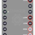
Circuit exposure unit "QK1-6841" <> Arduino:
- red <> D9
- green <> D10
- blue <> D11
- 6V (in my case black colored cable) <> 5V without DC Step-Up extra component
It had a WOW effect on me!


Comments