

Hardware components | ||||||
| × | 1 | ||||
| × | 1 | ||||
_ztBMuBhMHo.jpg?auto=compress%2Cformat&w=48&h=48&fit=fill&bg=ffffff) |
| × | 1 | |||
 |
| × | 1 | |||
Software apps and online services | ||||||
 |
| |||||
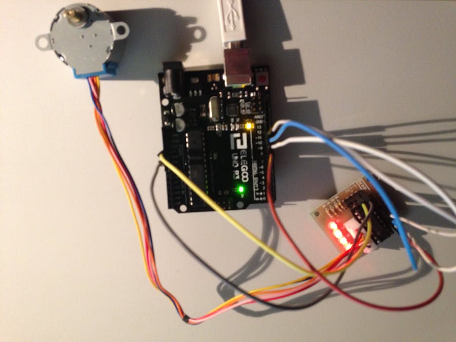
Today we look at the control of a stepper motor, and influence the rotation speed via inputs of the serial monitor.
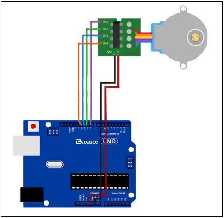
Following the schematic of the manufacturer from its instruction lesson number 23, the set-up with the additional components in the set can be quickly solved.
Just connect the prefabricated cable with the enclosed driver board. Here, errors are excluded: the cable harness only fits in one direction into the provided sleeve. Do not follow the color scheme of Schematic. In my opinion it is a shift register. On the head side, GND and + 5V are removed and applied to the device. Importing the necessary libary from CD will import additional sample sketches. The suggested original code is immediately ready for use and moves the arm slightly clockwise and backwards.
As far as good: I did not enter a deployment area promptly, which I could have used a stepping motor. The difference to a normal electric motor, which was also attached to the set and in another project, was not clear to me immediately.
Presumably, the "steps" in which the arm rotates can be very precisely and granularly influenced by means of a potentiometer.
For a celebration of the end-of-the-day building is quite interesting, but whether the stepper engine will last long in a real craft project I dare to doubt: the engine was already warm on his first mission and I was anxious about his electronic life.
In addition, I missed a few extra components to make the arm movement visually more recognizable, such as an adapter to accommodate the propellers from another engine project.
Information about a servo motor is available here.
You will find more under my account.

Comments