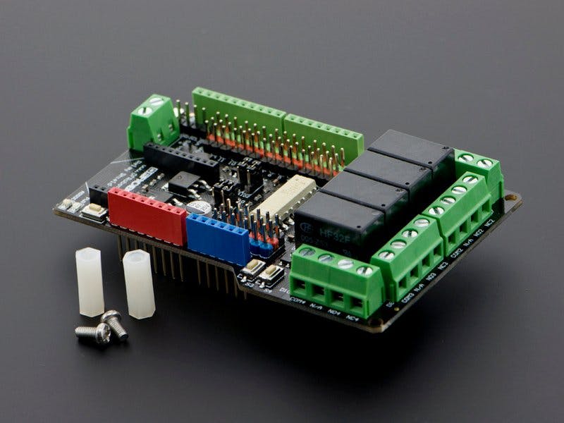
With a relay circuits can be switched with a different voltage than is necessary for the operation of the Arduino. And how easy it can be with a matching shield for the Arduino, you'll learn here.
When I put the Relay Shield on an Arduino Uno for the first time, I first had to smile for myself: there were actually two PINs on each side too many.
This can certainly be explained with the compatibility with other Arduino boards, but a mega is just not available to me. The product page also lists no special boards and so I find the note "Compatible with Arduino UNO Rev3" a bit poor.
No matter - for a first test with my room fountain to switch a 4 colored LED via 12V I do not need these PINs. We focus on using one of the relays.
The default assignment for addressing the 4 relays can be easily changed via jumper. This is also not necessary here and so we start with D2, D7, D8 and D10.
The shield has 4 buttons (S1-S4), so that a connection test is also possible without uploaded sketch.
With the help of Power DC adapters, I have connected a Y-cable to both the Arduino and Relay1. In my setup I use the green terminal adapters COM1 and NO1, respectively the plus pole. This means that I use the relay like a light switch and then turn on my 4 LEDs when the circuit is closed.
#define relay1 2
#define relay2 7
#define relay3 8
#define relay4 10
void setup() {
Serial.begin(9600);// setup Serial Monitor to display information
pinMode(relay1, OUTPUT);// connected to Relay 1
pinMode(relay2, OUTPUT);// connected to Relay 2
pinMode(relay3, OUTPUT);// connected to Relay 3
pinMode(relay4, OUTPUT);// connected to Relay 4
}
void loop() {
digitalWrite(relay1,HIGH);// turn relay 1 ON
Serial.println(" Relay 1 ON");
delay(3000);// keep in relay 1 On for 3 seconds
digitalWrite(relay1, LOW);// turn relay 1 OFF
Serial.println(" Relay 1 OFF");
delay(3000);// keep in relay 1 OFF for 3 seconds
}
With this "Hello World"-example I turn the Relay1 on Default D2 for 3 seconds on and off.
The example sketch offered for download on the product page is much more modern: Here, the Serial Monitor can be accessed by setting the digits 1-4 to the individual relays with a setting of 57, 600 baud.
Appropriately, you will find in the sketch the via "case" command possible reaction to it.
case '1':
        Serial.println("Relay1");
        val=digitalRead(relayPin[0]);
        val=!val;
        digitalWrite(relayPin[0],val);
        break;
With this we quickly approach the question, can the shield also be controlled via radio? The shield has room to hold an XBee device.
Unfortunately, in my case, Digi's configuration software - the XCTU - has not been able to detect my two devices - Pro S2B and Pro S1. If someone wants to help me - feel welcome!


_ztBMuBhMHo.jpg?auto=compress%2Cformat&w=48&h=48&fit=fill&bg=ffffff)


Comments