


Hardware components | ||||||
 |
| × | 1 | |||
 |
| × | 1 | |||
| × | 1 | ||||
 |
| × | 1 | |||
| × | 1 | ||||
Software apps and online services | ||||||
| ||||||
Hand tools and fabrication machines | ||||||
| ||||||
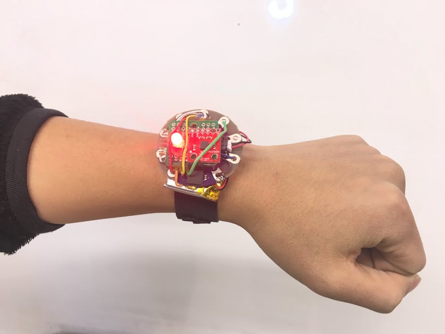
Our goal is to create a wearable wristband which can notify the user through vibrator and RGB LED when user's personal belonging is out of range.
For stage one, we created a prototype which can be modified into a wearable device. The prototype is based on Simblee LilyPad.
It's my very first time to hack on an electronic project. So, I will also explain my learning experience along the project itself.
Simblee Lilypad Features
- ARM Cortex M0 processor
- Bluetooth® Smart Stack built-in
- Integrated Antenna
- FTDI Programming Header
Components in the prototype
- Simblee LilyPad
- Vibration Motor
- Polymer Lithium Ion Battery-850mAh
- Triple Axis Accelerometer-ADXL335
- RGB LED
Rishabh and I decided to divide the work into two parts by components. I worked on the Triple Axis Accelerometer and the RGB LED. Rishabh worked on the Vibration Motor and the Polymer Lithium Ion Battery with Simblee LilyPad.
As we only had one Simblee LilyPad, I worked on the accelerometer and RGB LED based on the SparkFun Pro Micro which was given in class. After I finished my part, we put every component with the Simblee LilyPad.
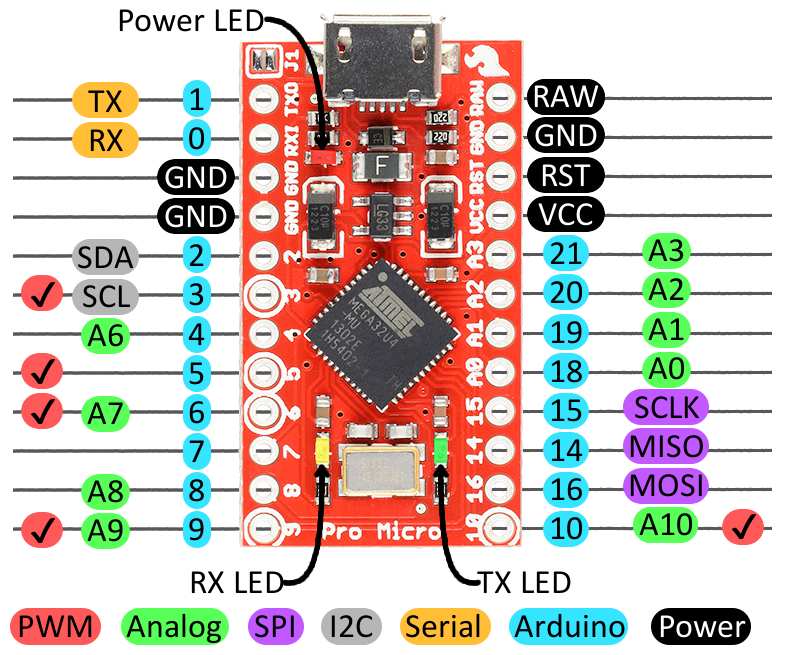
How to use Pro MicroThe first step for me is to learn how to use Pro Micro in Arduino IDE. I read through the SparkFun Pro Micro Hookup Guide. There are several points I would like to hightlight in this blog.
- Understand The Pinout. As a beginner, it was a little hard for me to understand the multi-functions of the same pin and the differences between Analog Pins and Digital Pins. It's the very first step to do before connecting Pro Micro with other sensors. I learned how to connect X, Y, Z, pins on the Accelerometer to certain pins on the Pro Micro!
- Installing the Arduino Addon to the Arduino on the laptop. Download the Pro Micro addon files, extract the files, then put the files into the Arduino sketchbook folder. For many new users like me, you need to point the Arduino IDE board manager to a custom URL first.
- Blinkies Sketch It was the first sketch which I uploaded to my Pro Micro. RX and TX LEDs take turns blinking on and off every second. I was really happy to see that!
- Soldering the Pro Micro with two headers on two sides. Each header should have 12 pins which connect with 12 pins on the Pro Micro. Rishabh taught some tricks to make the connecting spots smooth.
After I learned how to use Pro Micro, I started to make the accelerometer work with Pro Micro. Slightly different process like leanring Pro Micro, there is no hookup guide for the ADXL33 on Sparkfun website. However, I look into the bildr.blog
It was a quit smooth process to learn how to use the acceleromenter. Firstly, I read the blog on the bildr.blog, then I know that x ,y ,z connectors just connect to the 0, 1, 2 analog input pins on Pro Micro. In order to connect the two components, I need a breadboard, many wires with headers and solder the header with the acceleromenter. I got all needed materials at BTU lab.
Understanding how breadboard work is essential to build the wire connection. All holes in the same row is already connected. All holes in the same column is independent.
I connected the X pin to 0 analog pin on the Pro Micro, the Y pin to 1 analog pin on the Pro Micro, the Z pin to 2 anglog pin on the Pro Micro. Then, I connected the Pro Micro with mini USB cable. Futhermore, they operated at the same voltage, we don't need to put any resistor.
Then I uploaded the code through the Arduino with choosing the right board and port. This code simply calculates 0-360º values for X,Y & Z and prints it to the serial monitor. It showed on the following screen shot.
Making RGB LED flashing seem to be a very easy process for everyone. However, it wasn't easy for me as a beginner. There are so much more online tutorials related to RGB LED which made me so confused. They all say slightly different things based on various projects. For me, the two most important things I learned are what the RGB LED pinout looks like and what resistors I should use.
This is the RGB LED pinout. If it's a common anode LED, the longest pin should connect with VCC pin on Pro Micro. If it's a common cathode LED, the longest pin should connect with GND pin on Pro Micro. The LED which I was using in our project is a common anode LED. Therefore, I connect the longest pin with the VCC pin on the Pro Micro. Then, I connected the Red, Green, Blue pins through resistors to digital pins 6, 9, 10 on the Pro Micro ; all the three digital pins are PWM.
After couple times of testings, I found the right resistors to use. The resistors are 220Ω .
Then, I uploaded the RGB LEDs Arduino sketch to the Pro Micro.
Putting all components togetherAfter Rishabh and I completed our own part, we started to put all components together. They include a Simblee LilyPad, a vibration motor, a polymer lithium ion battery, a triple axis accelerometer and a RGB LED.


_3u05Tpwasz.png?auto=compress%2Cformat&w=40&h=40&fit=fillmax&bg=fff&dpr=2)


Comments