


Hardware components | ||||||
_wzec989qrF.jpg?auto=compress%2Cformat&w=48&h=48&fit=fill&bg=ffffff) |
| × | 1 | |||
 |
| × | 1 | |||
Software apps and online services | ||||||
 |
| |||||
Hand tools and fabrication machines | ||||||
 |
| |||||
Connect the various modules that make up the system respecting this diagram attached in the SCHEMATICS section (at the bottom of the page).
to print the imaginbot 3D controller circuit
Download Gerber file to build the circuit
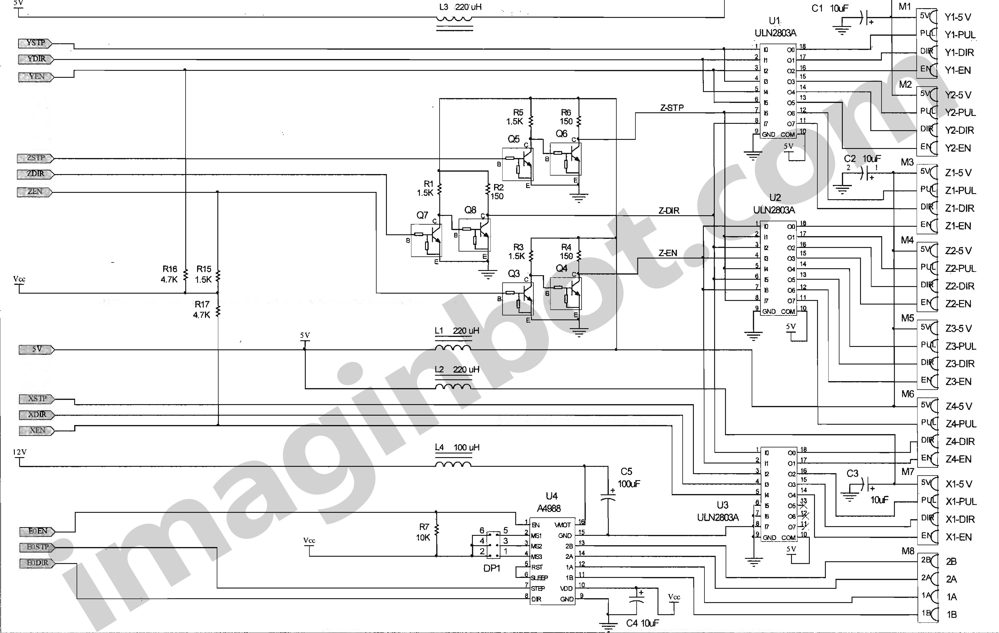
CONTROLLER CARD
Use a six-wire cable to connect the power supply of the controller board (POWER SUPPLY connector) to the power supply board (POWER SUPPLY connector).
You can also use three pairs of cables.
Connect a common USB cable directly to the Arduino USB port.
(CONNECTORS FROM M1 TO M7)
Use the four-wire cable for signals respectively:
Y1 (M1) and Y2 (M2) connectors: driver cables of the 2 motors on the Y axis.
Connectors Z1 (M3), Z2 (M4), Z3 (M5), Z4 (M6): driver cables of the 4 Z-axis motors.
Connectors X1 (M7): X-axis motor driver cables.
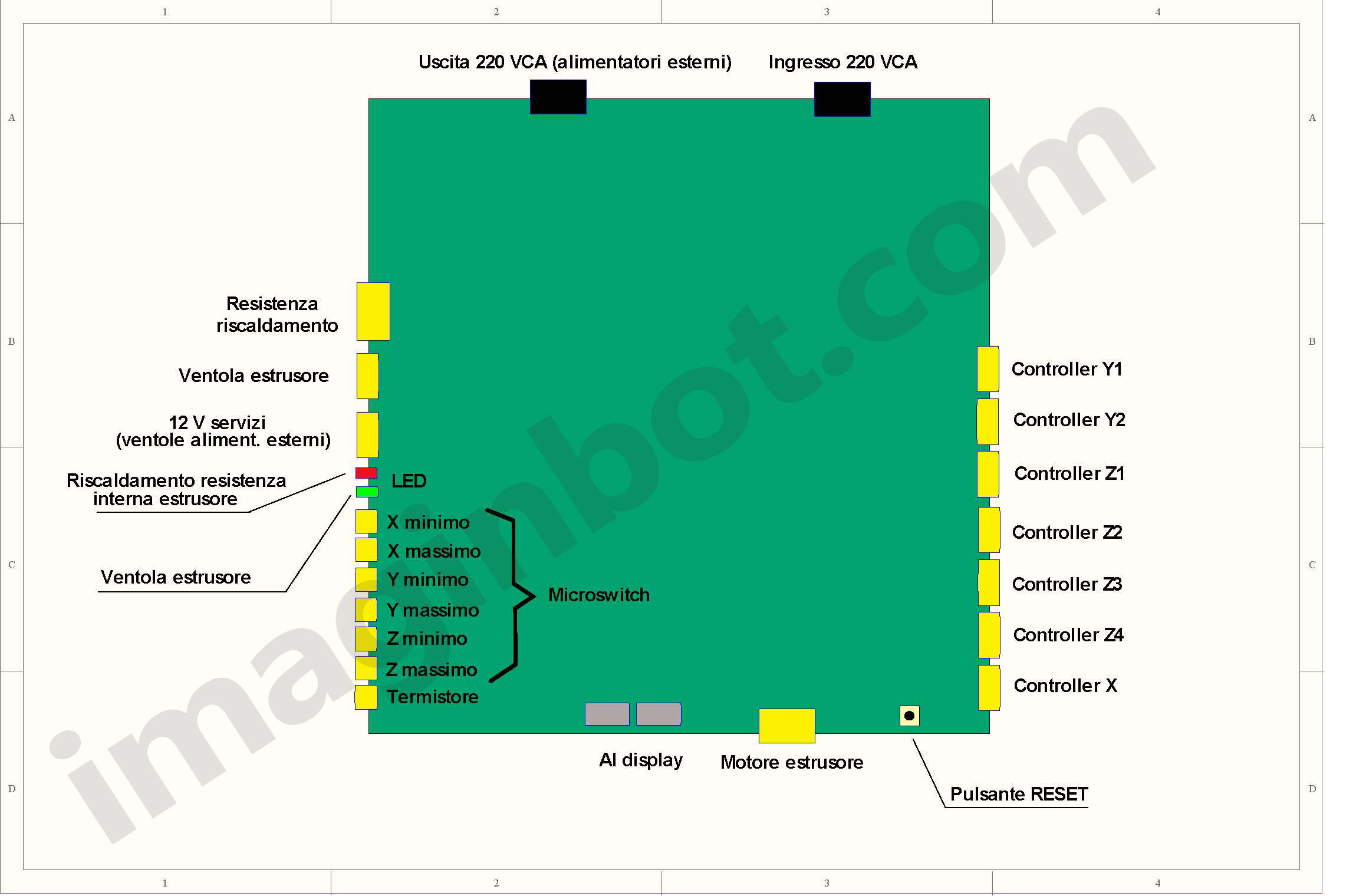
Follow this table for connecting the driver cables:
Screen printing on card --- Color
5V ---------------------- Red
PUL --------------------- Green
DIR --------------------- Yellow
EN ---------------------- Blue
The connectors are intended for the various drivers and can be wired with 0, 5 mm2 wire.
It is a good idea that the wire is not spirally wound (twisted) on the 4 connections relative to each driver.
The driving capacity of the various axes is expressed by the following table:
Axis-Connectors - Piloting capacity
X --------- M7 -------------- 1 driver
Y ------- M1, M2 ----------- 2 drivers
Z ---- M3, M4, M5, M6 ----- 4 drivers
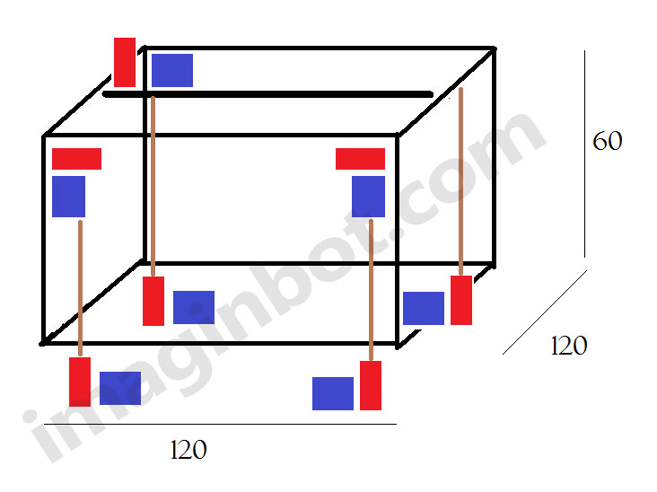
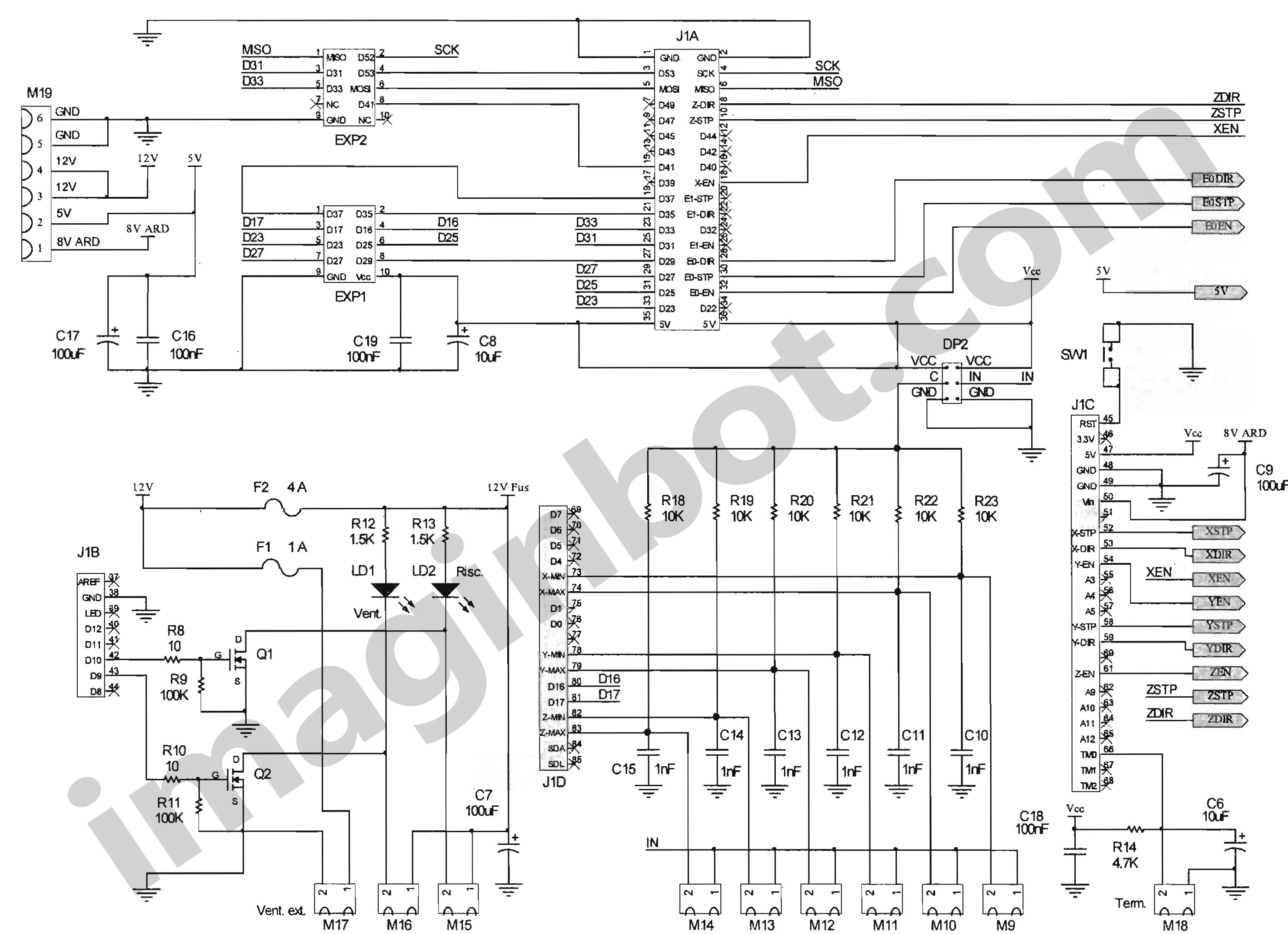
Use the two-wire cable to connect the limit switches respectively:
X-MIN (M9) and X-MAX (M10) connector: minimum and maximum X-axis limit switch.
Y-MIN connector (M11) and Y-MAX (M12): minimum and maximum Y-axis limit switch.
Z-MIN connector (M13) and Z-MAX (M14): minimum and maximum Z-axis limit switch.
The extruder group includes several cables:
EXTRUDER connector (M8): Extruder four-wire stepper motor cable.
RISC connector (M15): Two-wire heating element cable.
TERM connector (M18): Two-wire thermistor cable.
VENT connector (M16): Two-wire fan cable (observe polarity).
This connector transfers the command pulses to the extruder's stepper motor.
Having to support about 1 A of current for each pin it is good to be wired with wires not less than 1 mm2 (18 AWG).
If the cable length exceeds 1m it is necessary to increase the section to 1.2 mm2.
(M15 CONNECTOR)
The 12 VDC power supply portal connector on the extruder heating resistance.
The wires must have a cross-section of at least 1.5 mm2.
Enabling is indicated by the red LED.
The connector collects the thermistor connections inside the extruder.
It is important that in the event of a connection coming from the thermistor is connected directly to the metal parts, it is connected to the right pin (if viewed from the front).
The right pin is grounded and can be distinguished in the general drawing because it has a square pad.
If in doubt, it is advisable to check whether one of the wires related to the thermistor really has a direct connection on the metal parts (extruder) and, in this case, proceed as indicated.
This connector controls, via software, the fan present on the extruder.
The wires can be of section 0, 5 mm2.
The enabling of this fan is indicated by the green LED.
There are 12 service VDCs for a maximum current that can be drawn equal to 0, 4 A.
The polarity is marked with the "+" symbol on the screen printing.
This terminal can be used to connect any fans not controlled by the software (always active) also intended for cooling external power supplies.
The connectors have the task of connecting the display-encoder unit to the board.
Connect the 12864 display via its 10-wire flat cables.
Connect the first cable to the EXP1 connector and the second cable to the EXP2 connector.
Respect the right direction on both sides by orientating the cleat on the cable connector towards the slot on the connector on the board.
WARNING!
An incorrect arrangement of the same (can easily lend itself to being reversed between them) can cause irreversible damage.
The maximum length of the flat cable should not exceed 25cm.
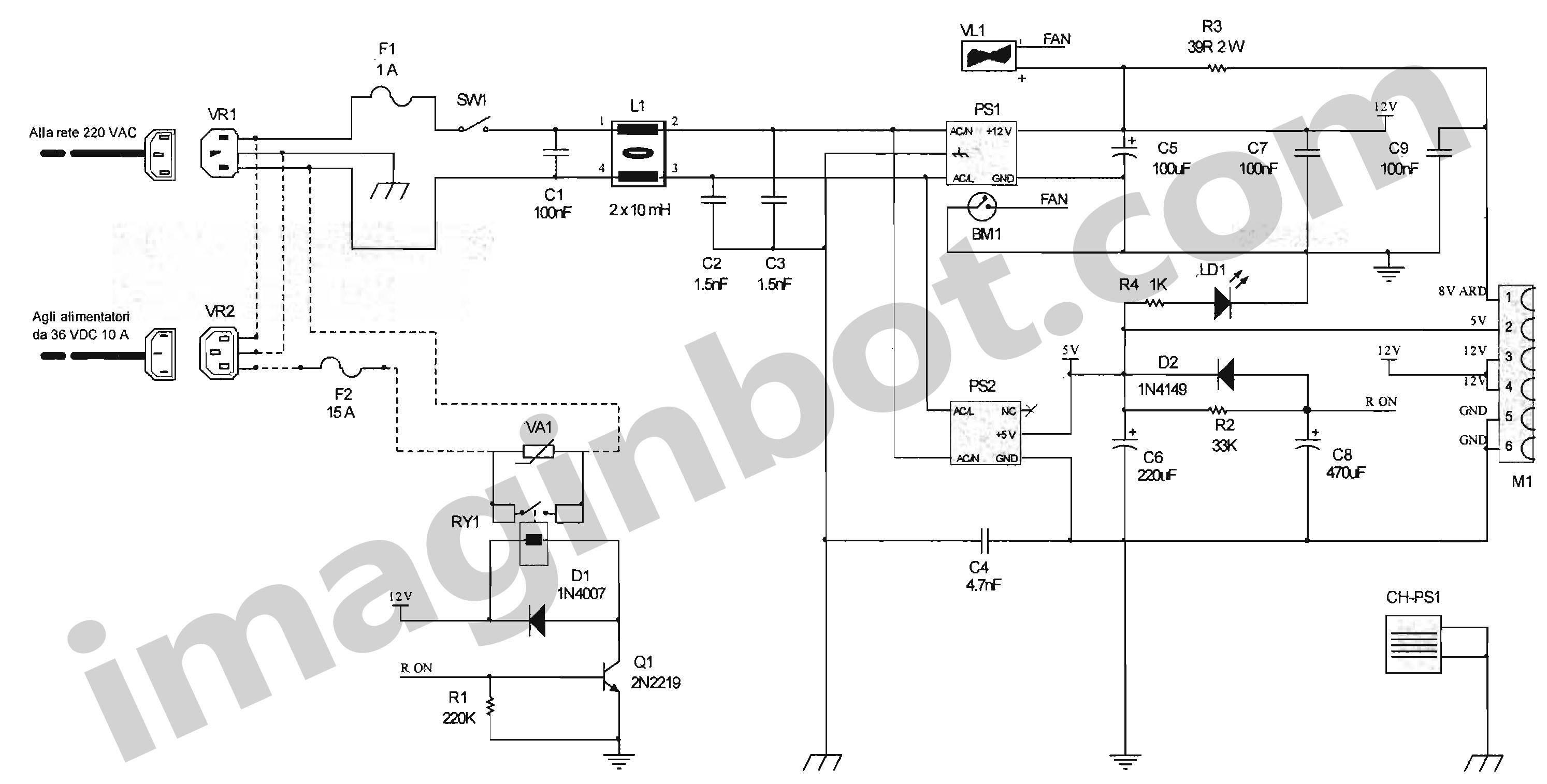
POWER SUPPLY CONNECTOR
INPUT FROM ELECTRICITY NETWORK
Present on the front panel, it supplies AC power to both the external board and the power supplies.
It can be wired with a female connector for IEC type tray, commonly available.
The cable must not have a section less than 1.2 mm2 and must be equipped with earth.
A common 220VAC cable for fixed computers can be used.
Before connecting the cable, make sure that the main switch is OFF and that the card is inside an insulating container so as to protect.
Use the cables recommended in the table at the end of this document to connect the two boards together, Controller and Power Supply.
Connect the 220VAC inputs of the two RC filters with a common monitor cable to the connector on the 220VAC output power supply board.
Each cable must have three conductors:
Phase (brown).
Neutral (blue).
Earth (green and yellow).
The inputs of the filter 1 and filter 2 can be connected in parallel.
OUTPUT POWER SUPPLY CONNECTOR
It is present on the front panel.
This is the connector that returns the 220VAC network to external power supplies.
It can be wired with a male plug for IEC type tray, commonly available.
The cable must not have a section less than 1.2mm2 and must be equipped with earth.
Connect the 220VAC output of the RC filters with four common cables for electrical systems to the four external power supplies:
Exit from Filter 1: power supply 1 and 2.
Exit from Filter 2: power supply 3 and 4.
Each cable must have three conductors: Phase (brown).
Neutral (blue).
Earth (green and yellow).
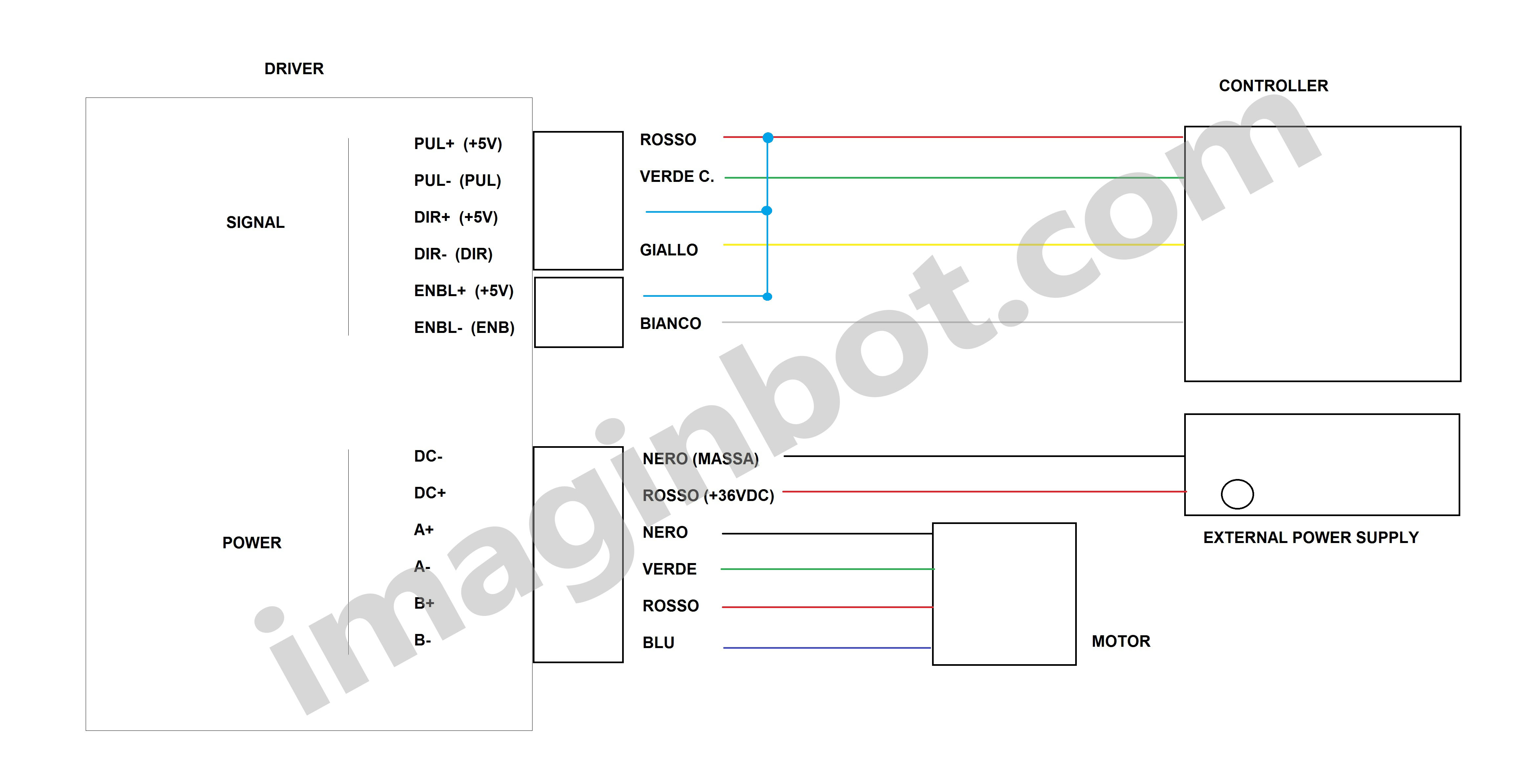
Use a two-wire cable for each driver respectively (observe polarity):
Power supply 1: Z1 and Z2 axis drivers.
Power supply 2: Z3 and Z4 axis drivers.
Power supply 3: Y1 and Y2 axis drivers
Power supply 4: X1 axis driver.
Use the guinea pigs two wires coming from the DC outputs of the power supplies for the power supplies of each driver (positive and negative).
Use the four-wire cable from the controller board for each driver's signals.
On the driver connectors, make the connections and bridges as shown in this diagram:
to print the imaginbot 3D controller circuit


Comments