

Hardware components | ||||||
| × | 1 | ||||
 |
| × | 1 | |||
 |
| × | 1 | |||
Software apps and online services | ||||||
_4YUDWziWQ8.png?auto=compress%2Cformat&w=48&h=48&fit=fill&bg=ffffff) |
| |||||
| ||||||
Hand tools and fabrication machines | ||||||
 |
| |||||
It all started when I was browsing an online electronics equipment auction. Somehow I ended up buying a Agilent 6626A. I'm not really sure why I bought it, but it was cheap so why not?
But oh boy when I went to pick it up... This power supply is a real chunky one.
So now I was sitting there with this huge instrument, covering half my desk thinking, what to do with it. I started browsing the manual and saw something about a command interface to the power supply. This was the first time I heard of GPIB.
I started researching how I could communciate over GPIB with the instrument and found the really awesome https://github.com/Twilight-Logic/AR488 project that is an GPIB<->UART converter. So I ordered some PCBs and the necessary components and about 2 weeks later I could send commands to the instrument from my computer!
Taking it to the next levelI now saw all the possibilities I could do with this power supply.
The four outputs of the power supply was at the back side, not very easy accessible, so that got me thinking... Let's do a breakout PCB to which I can route the outputs on the back to a new front panel.
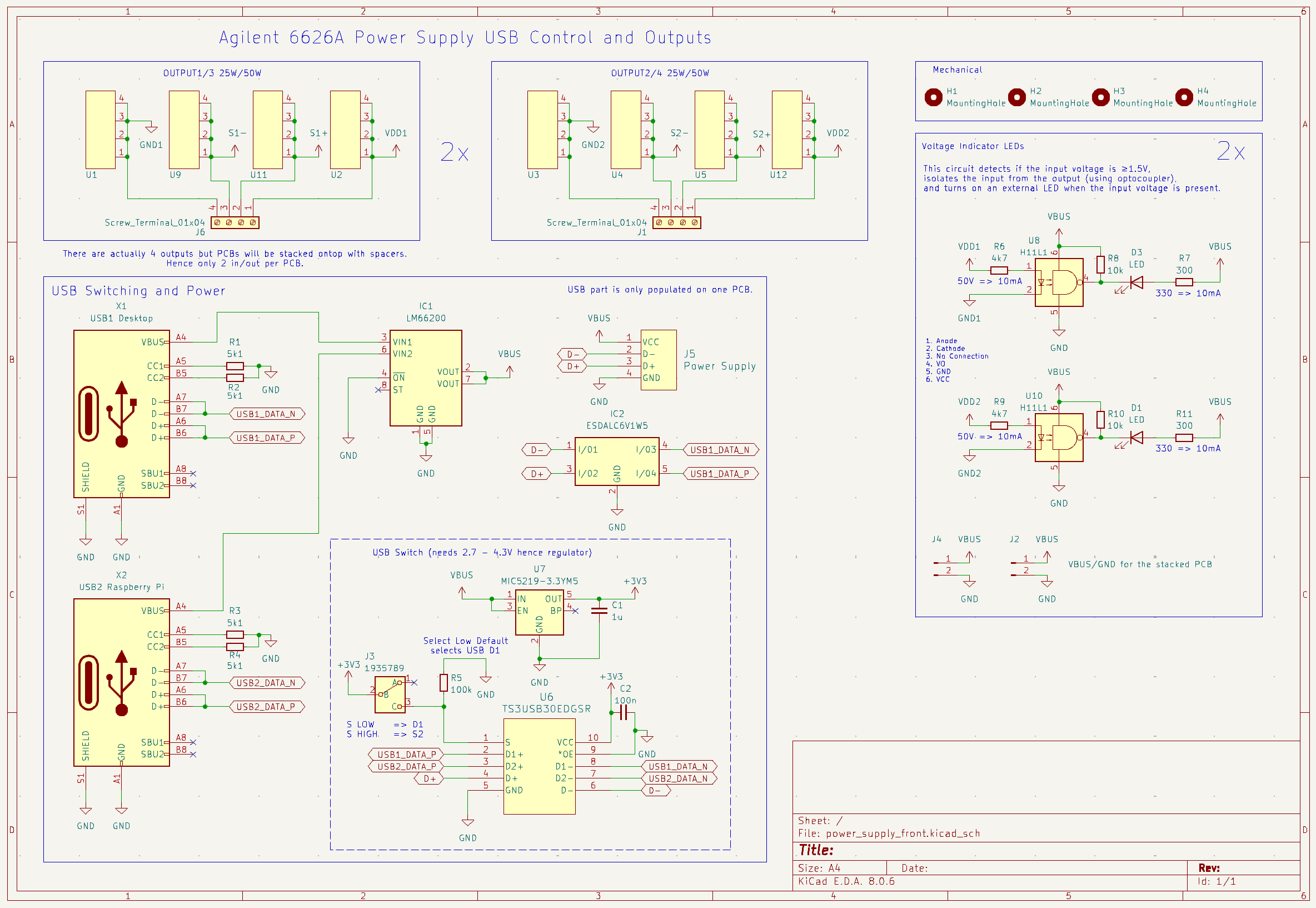
The PCB feature creap happened and at the last this are the PCB features:
- USB A connector that connects to the power supply through the GPIB <-> UART bridge.
- Two USB C connectors that can connect to different hosts, such as a computer in addition to the Raspberry Pi.
- USB switch (controlled through a switch) that routes the GPIB USB to either of the two USB C connectors.
- 4 optocouplers controlling 4 LEDs (one for each output) to indicate if power is enabled or not.
- Due to the four outputs having separate grounds, I use optocouplers to isolate the LED from the actual output.
The PCB uses extra thick copper layer together with wide traces mirrored on both top and bottom layer for high current capabilties.
While waiting on the PCB I started with a UI. I used PyQt5 to design a decent looking UI to graphically interact with the power supply. Behind the scenes GPIB commands are sent to the power supply to make it do what we want.
The control interface is quite simple. For example to set output 1 to 5V, max 0.1A it's as simple as this:
VSET 1,1.8000
ISET 1,0.1000
You can also query stuff such as the actual voltage at the output and current being drawn. This is what's being used to display the realtime plots.
VOUT? 1
<now read response>
IOUT? 1
<now read response>The sensing inputs are also routed to the new front panel. The default way to use them is to short the V_out to Sense+ and GND to Sense- on the front panel using a simple 2-1 banana plug. When these are connected, the power supply's sense feature will compensate for voltage loss in the cables running from the back of the power supply to the new front panel.
To allow for more advanced use, simply remove the 2-1 banana plug, giving you free access to the Sense+ and Sense- on each output.


_t9PF3orMPd.png?auto=compress%2Cformat&w=40&h=40&fit=fillmax&bg=fff&dpr=2)


_Ujn5WoVOOu.png?auto=compress%2Cformat&w=40&h=40&fit=fillmax&bg=fff&dpr=2)

Comments