

Hardware components | ||||||
 |
| × | 1 | |||
 |
| × | 16 | |||
 |
| × | 64 | |||
_ztBMuBhMHo.jpg?auto=compress%2Cformat&w=48&h=48&fit=fill&bg=ffffff) |
| × | 1 | |||
 |
| × | 1 | |||
 |
| × | 20 | |||
| × | 1 | ||||
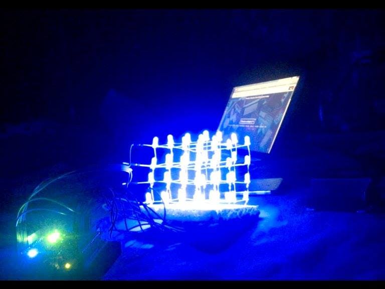
This is an amazing 4x4x4 LED cube connected to your smartphone using the 1sheeld and arduino uno. Let the music control ...
How to construct the LED cube:
Follow this instructable to construct the LED cube. You only need step 3, step 4 and step 5. You need to have some basic soldering knowledge.
http://www.instructables.com/id/LED-Cube-4x4x4/
**You will not need the components in the instructable. for the needed components refer to the components list below.
Theory of operation:
Running a wire to the anode of each led is obviously impractical.
One possible solution is to split the cube into 4 layers, each layer consists of 16 LEDs.
All the LEDs in a vertical column share a common anode (+).
All the LEDs on a horizontal layer share a common cathode (-).
In order to light up a specific LED, just supply GND (-) to the layer which contains that LED and then supply 5V (+) to the column which contains that LED.
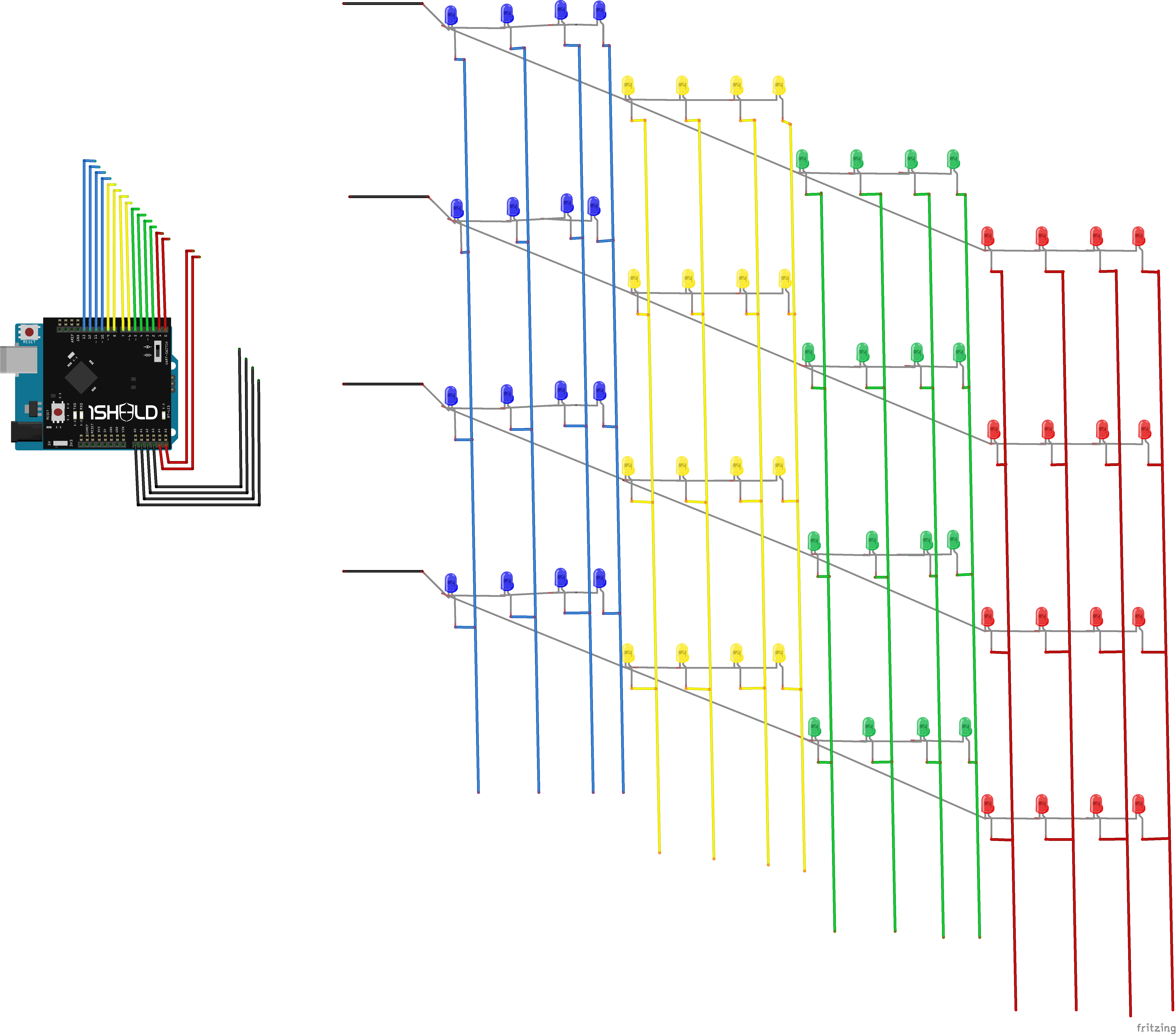
Wiring:
After constructing the cube, you should have 16 pins to control the columns and 4 pins to control the layers.
Ω-Connect each column control pin to a 220Ω resistor in series, the other terminal of the resistor is connected to the 1sheeld mounted over the arduino board.
*** I tried connecting the wires directly to the 1sheeld & arduino without resistors and it actually worked, but it is not recommended.
*The column control pins are connected in order to digital pins from 13 to 0 and analog pins A4 & A5. (Refer to the diagram)
*Each pin control thee LEDs in that column, so you are free to connect the columns with any combination.
-Connect the layer control pins to analog pins A0, A1, A2 & A3.
*According to my code, the lower layer is connected to pin A0, then the next layer is connected to pin A1, then the next layer is connected to pin A2 and the highest layer is connected to pin A3. (Refer to the diagram)
-After connecting the wires to the 1sheeld and arduino, you can now upload the code and then connect your smart phone to the 1sheeld.
*If you are not familiar with 1sheeld you can follow this tutorial first.
http://1sheeld.com/tutorials/getting-started/


Comments