



Hardware components | ||||||
| × | 1 | ||||
| × | 1 | ||||
| × | 1 | ||||
Software apps and online services | ||||||
 |
| |||||
Hand tools and fabrication machines | ||||||
 |
| |||||
I wanted a compact way to measure fishing line using parts already on my bench: an ESP32-C3 SuperMini, a Hall module, a small OLED, magnets and a 3D printer. The result is a USB-powered counter with a large readout and a reset button. No custom PCB or pinch roller is required.
The prototype has been assembled and its display and counting function tested. Measurement accuracy and long-term reliability have not yet been quantified. The cover is an AI-retouched photograph with a cleaner background and lighting; the original photograph is included in the repository.
Download the complete MIT-licensed project on GitHub: firmware, 11 printable STL files, editable Fusion and STEP models, and assembly notes.
How it measures lengthWrap the fishing line once around the side wheel. Pulling the line rotates the wheel, and six magnets pass an A3144E Hall sensor. The ESP32 counts falling edges and multiplies the pulse count by a calibrated distance per pulse. This is a single-channel counter: either rotation direction adds length. It does not detect reverse movement.
The OLED shows meters in large digits, with two decimal places. P is the accumulated pulse count and H is the current Hall input level. Press the button to reset. The length resets after power loss, while the calibration coefficient is saved.
Parts and mechanical layoutThe electronics are one ESP32-C3 SuperMini, one 0.96-inch 128×64 SSD1306 I2C OLED, one HW-477 V0.2 A3144E Hall module, and one 6×6mm tactile button. The wheel uses six 3×1mm magnets, two bearings with 4mm bore, approximately 9mm outside diameter and 4mm width, plus a 4mm shaft.
The prototype shaft has a 20mm smooth section, 14.85mm of M4 thread, and a 6mm-diameter shoulder about 4mm long. Its total length is approximately 39mm. An M4 nut secures the shaft and a separately sourced shaft collar retains the wheel.
The body is 58×50×37.081mm. The modeled envelope including wheel, shaft and button is approximately 79×51.2×38mm, excluding the additional shaft collar. The wheel flange is 30mm in diameter, but the bare running core is 24mm. Do not use the flange diameter to calculate line travel.
Print and assembleStart with fit_coupon.stl. It contains bearing trial holes of 9.0, 9.1 and 9.2mm and a 3.2mm magnet pocket. The wheel model uses a 9.1mm bearing seat. Check the fit with your printer before printing the full enclosure.
The STL files have suggested print orientations. Inspect overhangs and add supports where needed. A 0.2mm layer height and three walls are a starting point, not a validated setting for every printer or material.
Mount the OLED and button in the upper shell and the C3 in the base. The complete Hall PCB sits inside the upper shell below the shaft. Gently bend its original long sensor leads to position the sensing face beside the magnet track; do not desolder the sensing head or force the leads with the retaining clamp. Keep the three leads insulated from each other and leave enough wire slack to open the case.
Use four 3×8mm plastic self-tapping screws for the housing, eight 2×6mm screws for the OLED, C3 clamp and button tray, and three 1.6×4mm screws for the Hall PCB and sensor retainer. Check head clearances against the detailed assembly guide. Install the bearings, inner-ring spacers and shaft, then confirm the wheel rotates freely.
All six magnets must present the same triggering pole to the sensor. Test their orientation and the actual sensing gap before gluing them. Between adjacent magnets the Hall signal must return high, otherwise pulses can merge.
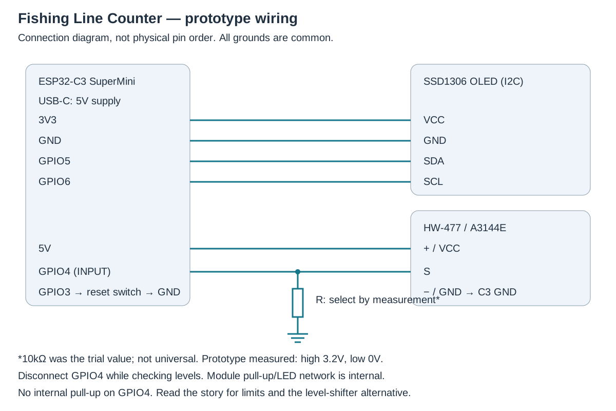
Wiring and the Hall signalPower the C3 through USB-C and connect all grounds together. OLED VCC goes to 3V3, GND to GND, SDA to GPIO5 and SCL to GPIO6. The reset button connects GPIO3 to GND using contacts that close only when pressed. Its internal pull-up is enabled.
The Hall module is powered from 5V. Its S signal reaches GPIO4 only after the output level has been checked and conditioned. GPIO4 is configured as a plain INPUT with no internal pull-up or pull-down. A3144 specifies a minimum supply of 4.5V, so 3.3V operation is not a reliable general solution.
Do not connect an unmodified 5V Hall-module output directly to the ESP32. On this particular prototype, S measured 3.73V without a magnet. Adding one resistor from S to GND reduced the measured high level to 3.2V; bringing a magnet near reduced it to 0V. A 10kΩ resistor was the trial starting point, but its final value was not independently rechecked.
This one-resistor approach relies on the module's existing pull-up/LED circuitry. It is not a voltage clamp and is not a universal recipe for every HW-477 board. Disconnect GPIO4 while measuring and verify levels under the actual supply and use conditions. A detached resistor can restore an excessive signal voltage. If you cannot characterize the module, use a suitable level translator instead.
A BSS138 level-shifter board is an alternative: HV to 5V, LV to 3V3, common GND, Hall S to HV1 and GPIO4 to LV1. Do not retain the prototype pull-down in this alternative. Space for an extra board has not been validated in this enclosure.
Build and upload the firmwareInstall PlatformIO and download or clone the GitHub repository. In its root directory, run:
pio run -d firmware
pio device list
pio run -d firmware -t upload --upload-port YOUR_PORT
pio device monitor -b 115200 -p YOUR_PORT
Replace YOUR_PORT with the detected serial port. If automatic upload fails, hold BOOT while connecting USB, then release it and retry. The firmware probes OLED addresses 0x3C and 0x3D automatically. The published source has been compiled successfully; the large-digit version was also flashed and tested on the prototype.
Verify counting, then calibrateRotate the wheel slowly through ten full turns. With six magnets, P should increase by 60. Repeat at the intended operating speed, then check that the button resets the count. Fix missed pulses, continuous triggering or slipping before calibrating.
The default coefficient is 14.66076572mm per pulse: pi × 28mm ÷ 6. That assumes a 28mm effective tread, not the 30mm flange. For a bare 24mm core and six magnets, the geometric starting value is approximately 12.56637061mm per pulse. Line thickness and any added friction layer change the effective diameter.
Mark a known length of line, for example 5m. Wrap it normally, bring the first mark to a fixed reference and reset. Pull until the second mark reaches the same reference. Calculate: new coefficient = current coefficient × known length ÷ displayed length. Send the result over the 115200-baud serial monitor with a newline:
MM 12.56637061This command is an example starting value, not a universal calibration. Wait for the Saved message, reset and repeat the measurement several times. ZERO is also available as a serial reset command. Two decimal places describe the display format, not guaranteed centimeter accuracy.
Files and next stepsFirmware · Printable STLs · Fusion and STEP · Detailed assembly notes · Original prototype photograph.
The most useful next tests are repeatability over known line lengths, slip behavior with different line materials, and reliable Hall triggering at different pulling speeds. The design is available under the MIT license for others to build and improve.


Comments