

ICStation team introduce you the NRF24L01 Wireless Motor Speed Control System. This system works under DC 5V voltage. It uses the NRF24L01 Wireless Module to transmit speed control data and the Hall Sensor to detect the real rotate speed. This design uses the PWM duty cycle to modulate and realize the speed control.What’s more, It can be used in situations which do not need high speed control precision, such as automatic control of curtains.
Functions:
1)When initialize the sending part, the LCD1602 board displays the characters of the original PMW data and the speed which is with zero. The receiving part will control the wireless transmission of data and displays the real rotation speed after the receiving part finishes the initialization.
2) When the Receiving Module works, the rotate speed of the Motor will change according to the data which is transmitted by the sending part. The Hall Sensor Speed Measure Module begins to detect the rotate speed and the LED light of the Hall sensor lights. Meanwhile, the Wireless Module of the receiving part will send the detected rotate speed data back to the Sending part.
3) For the sending part, we need four keys (K0, K1, K2, K3) in the keyboard to change the speed of the motor. The associated functions of the four keys as following:
① Press the key KO for the first time, the motor moves as the first gear of speed; press the key KO again, the motor moves as the second gear of speed; the third time when we press the key KO, the motor moves as the third gear of speed; the,forth time when we press the K0,,the motor moves as the first gear of speed.
② Press the key K1, we can switch the rotate speed of increasing or reducing.
③ Press the key K2, we can change the rotate speed to five more or less.
④ Press the key K3, we can change the rotate speed to ten more or less.
Code for reference:
http://www.icstation.com/newsletter/eMarketing/NRF24L01_Control_Code.zip
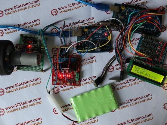
Step 1: Components list:
Step 2: Schematic Diagram
Step 3: The connection of receiving part
1. Connect the NRF24L01 Wireless Module to the ICStation UNO.
- SCK – Digital pin 13
- MOSI – Digital pin 11
- CS – Digital pin 7
- CS – Digital pin 8
- MOSI – Digital pin 12
2. Connect the L298N to the ICStation UNO
- VMS – 7.2V Anode
- GND – Cathode
- INA – GND
- INB – VCC(5V)
- ENA – Digital pin 5
3.Connect the Hall Module to the ICStation UNO
- DOUT – Digital pin 3
Step 4: The connection of sending part
1. Connect the NRF24L01 Wireless Module to the ICStation MEGA2560
- SCK – Digital pin 52
- MOSI – Digital pin 51
- MOSI – Digital pin 50
- CS – Digital pin 9
- CE – Digital pin 8
2. Connect the 1602 LCD Module to the ICStation MEGA2560
- SCL – A5
- SDA – A4
3. Connect the keyboard to the ICStation MEGA2560
- S1 – Digital pin 22
- S1 – Digital pin 23
- S1 – Digital pin 24
- S1 – Digital pin 25

Comments