

Hardware components | ||||||
| × | 1 | ||||
 |
| × | 1 | |||
 |
| × | 2 | |||
 |
| × | 1 | |||
Software apps and online services | ||||||
| ||||||
The project shows how to control a simple external LED circuit using an STM32 Nucleo-64 F401RE development board and the RIOT operating system.
The goal is to provide an example on the low-level GPIO (General-purpose input/output) peripheral driver of RIOT through which we can have a platform independent basic access to an MCU's input/output pins.
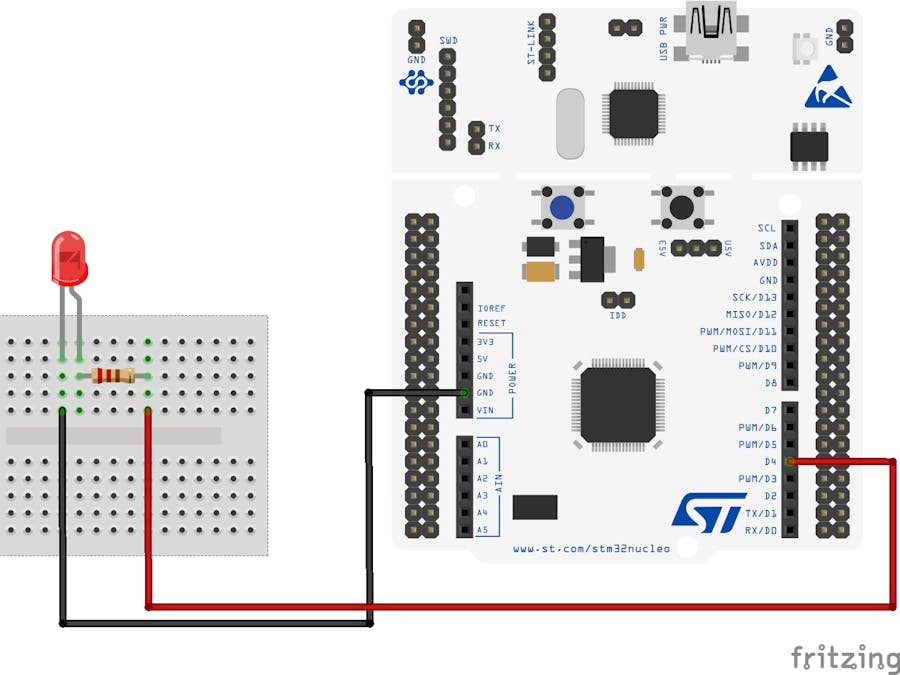
Wiring the hardware componentsNotice that the LED has two pins: one of the pins is longer. The longer pin is the positive end of the led and is called the anode. The other pin is called the cathode.
Connect one side of the resistor with the anode pin of the LED, and the other side of the resistor with the GND pin of the STM32 Nucleo board.
Connect the cathode pin of the LED with the D4 pin of the STM32 Nucleo board.
To create a new application you need to create a directory containing two files: (1) the Makefile and (2) the main.c file.
At minimum the Makefile should define the following basic aspects of the application:
- The name of the application (
APPLICATION) - The location of the RIOT base directory (
RIOTBASE) - Additionally, it is required to include the
Makefile.includefrom theRIOTBASE
# A simple name of the application
APPLICATION = ledext

# This has to be the absolute path to the RIOT base directory:
RIOTBASE ?= $(CURDIR)/../../RIOT

include $(RIOTBASE)/Makefile.include
Within the Makefile we also define that the application will use the RIOT low-level GPIO peripheral:
USEMODULE += periph_gpioWe wish to make the LED blink periodically. For this reason we will use the RIOT xtimer module that provides a high-level API to multiplex the available timers.
USEMODULE += xtimerThe above are enough to setup a new application. More details can be found on the RIOT documentation.
The next step is to create the main.c file where the main code of the application is defined.
First we include the headers of the GPIO peripheral and the XTIMER module. We also include stdio.h for printing debug messages.
#include <stdio.h>

#include "periph/gpio.h"
#include "xtimer.h"
The GPIO interface is intentionally designed to be as simple as possible, to allow for easy implementation and maximum portability. All modern micro controllers organize their GPIOs in some form of ports, often named 'PA', 'PB', 'PC'..., or 'P0', 'P1', 'P2'..., or similar. Each of these ports is then assigned a number of pins, often 8, 16, or 32. To access a pin, the _GPIO_PIN(port, pin) macro_ should be used.
For the case of the STM32 Nucleo board used here, the mapping of the ARDUINO® Uno V3 connectivity headers with the MCU's internal pins can be found in the user manual UM1724 of the STM32 Nucleo F401RE board.
The figure below indicates that the D4 pin is connected to the PB port of the F401RE MCU at pin number 5.
The GPIO interface provides capabilities to initialize a pin as output-, input- and interrupt pin. Within the main.c file we need to use the gpio_init method to signal that pin PB5 should be initialized for output (GPIO_OUT) as follows:
gpio_t pin_out = GPIO_PIN(PORT_B, 5);
if (gpio_init(pin_out, GPIO_OUT)) {
    printf("Error to initialize GPIO_PIN(%d %d)\n", PORT_B, 5);
    return -1;
}
Now we can make the LED blink periodically as follows:
while(1)
{
  printf("Set pin to HIGH\n");
  gpio_set(pin_out);

  xtimer_sleep(2);

  printf("Set pin to LOW\n");
  gpio_clear(pin_out);

  xtimer_sleep(2);
}To compile the application, program the STM32 board and connect through the USB to receive debug information, we execute the following command:
make BOARD=nucleo-f401re flash termHere is what we should expected as output:
main(): This is RIOT! (Version: 2021.04-devel-200-g67e5a)
RIOT led_ext application
Control an external LED using RIOT GPIO module.
Set pin to HIGH
Set pin to LOW
More details on the code and insights on how the different modules of RIOT are used in this application can be found on the GITHUB repository.


Comments