

Hardware components | ||||||
_ztBMuBhMHo.jpg?auto=compress%2Cformat&w=48&h=48&fit=fill&bg=ffffff) |
| × | 1 | |||
 |
| × | 1 | |||
 |
| × | 1 | |||
 |
| × | 1 | |||
 |
| × | 1 | |||
 |
| × | 1 | |||
 |
| × | 2 | |||
 |
| × | 1 | |||
 |
| × | 1 | |||
 |
| × | 1 | |||
 |
| × | 1 | |||
 |
| × | 1 | |||
Software apps and online services | ||||||
 |
| |||||
Hand tools and fabrication machines | ||||||
 |
| |||||
We are going to control the brightness of a LED automatically. But we need to know some basics about our friends..... OpAmps. Therefore, I will give you a hint.
Operational amplifiersare linear devices that have all the properties required for nearly ideal DC amplification and are therefore used extensively in signal conditioning, filtering or to perform mathematical operations such as add, subtract, integration and differentiation.
An Operational Amplifier is basically a three-terminal device which consists of two high impedance inputs. One of the inputs is called the Inverting Input, marked with a negative or “minus” sign, ( – ). The other input is called the Non-inverting Input, marked with a positive or “plus” sign ( + ).The difference of two inputs will be enhainced by a gain.
Below we can see a type of amplifier. But we have many different types of OpAmps based on our purposes.
amplifies the difference between two voltages making this type of operational amplifier circuit a Subtractor unlike a summing amplifier which adds or sums together the input voltages.Amplifier's gain depends on the price of resistor we use. So, we can control the value of volts we can amplify in output.
For more: https://www.electronics-tutorials.ws/opamp/opamp_5.html
If we made the feedback resistor, Rƒ equal to zero, (Rƒ = 0), and resistor R2 equal to infinity, (R2 = ∞), then the circuit would have a fixed gain of “1” as all the output voltage would be present on the inverting input terminal (negative feedback). This would then produce a special type of the non-inverting amplifier circuit called a Voltage Follower or also called a “unity gain buffer”.
Elements that detect optics radiation and convert perspective electricity signal
Separated in :
"Window" at the top
• Often the Base, which is sensitive to light, does not
is connected (as in our circuit) and simply serves to generate electricity
in the transistor.
• In our circuit, its connection transistor is that of the common collector. THE
emitter is connected via one load on the ground and the collector on the voltage.
The exit is on the show.
• The circuit gives the output voltage that ranges from a low to a high price
is connected (as in our circuit)
http://m.eet.com/media/1049853/C0086-Table1a.gif
- Spectrum Response
- Lineality of signal output
- Sensitivity
- Response time to changes incident light
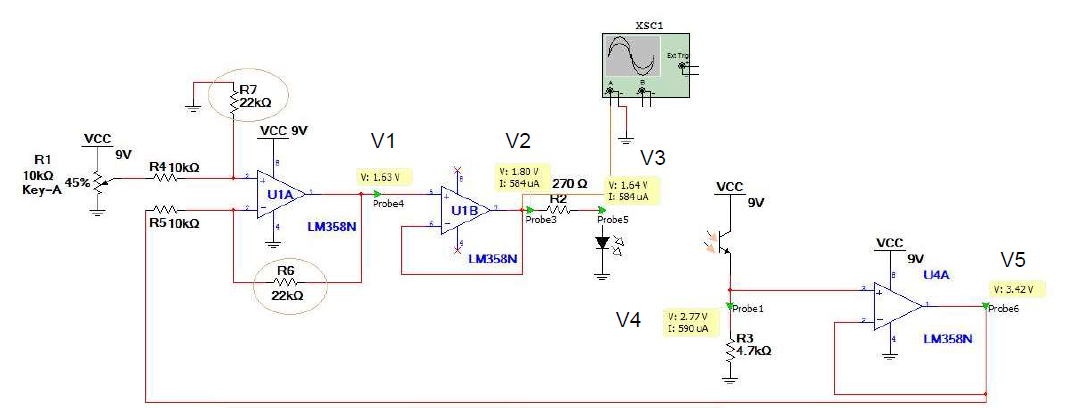
Closed loop of photoresistor control system. But first, we need to know some important things about manifacturing process.
As an input we use a potentiometer which gives different voltage values. The output is a result of the light that the phototransistor will receive and will convert it into voltage. It depends on both the geometric characteristics of the LED-phototransistor pair and the environmental conditions.For example natural light that affects the layout. The differental amplifier plays the role of controller as it controls the voltage that will supply the LED. So it controls the operation of both the LED and the phototransistor. The voltage follower acts as the actuator as it will supply the LED through it.
LED is the process as we want to control its brightness. The phototransistor plays the role of the sensor as it "feels" any fluctuation of the voltage through the photons it receives. So through the feedback it sends a signal to the controller depending on the conditions.
Anything that would prevent the sensor from taking measurement. Any obstacle (eg paper). Noise can be of many kinds. From our experience we have seen noise in jumpers due to their function as antennas. But it may also be due to other electronic components.
Even in an unwanted voltage that may interfere.
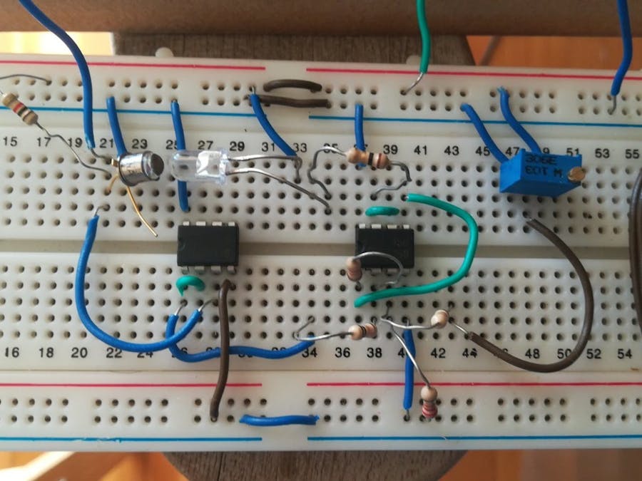
IMPORTANT: Install the LED and the phototransistor in opposite, close positions on the actual breadboard!
It is needed for the operation of 9 V at 8 and grounding at 4
So, we can see the chart from arduino voltage meter. We use arduino to make sampling of voltage prices to time for the LED and phototransistor. Below can observe the efficiency of system in case of effecting by external enviroment.
You can easily converter your arduino to voltage meter through serial plot. But I cannot show how to do that immidiately. Althought, I will share the code. Many tutorials, many ways! Try them out and have fun!


Comments