This project is the first step towards a larger scale integration of analog signals with a colorful and interactive display. Specifically, I plan to display output voltages and frequencies from my electric guitar to an LED matrix. This is actually the first time I have worked with an Arduino (I know, I've been under a rock) and I immediately recognize why it is such a popular development board.
I was given an Arduino Uno to work with, and since I was new to this board I started with a little research on how to use it. As you may know, Arduino has its own IDE. Arduino's website contains an extensive reference section for functions, data types, and syntax in the Arduino IDE. I chose to look at the analogWrite() function and the sample code it provided turned out to be a very simple start to exactly what I was trying to do.
This is what Daffy Duck's Arduino Uno would look like.
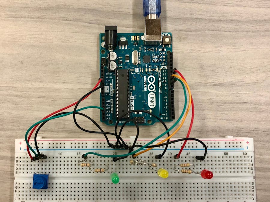
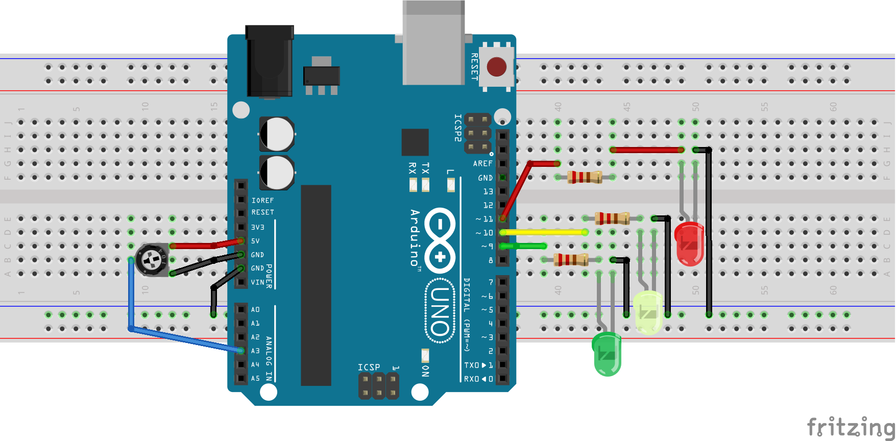
Getting started, the first step is generating an analog voltage that can be manually varied. For testing purposes, this is easiest with a potentiometer hooked up to the on board power supply and ground ports on the Uno. The output from the potentiometer is then sent to an analog input on the Uno; there's six to choose from. The greatest range is obtained using the 5V power supply, rather than the 3.3V supply, which will be discussed more later. Below, you can toggle between a view of the Arduino input ports and the external potentiometer connections.
1 / 2 • Input port A3 receives voltage from potentiometer (green wire). The red and black wires are connected to 5V and ground, respectively.
The Arduino Uno has a 10-bit analog to digital converter, or ADC for short (ha...short). This means that for a range of up to 5 volts, the ADC will map the input voltage to an integer value up to 1024 (the largest value in a 10-bit binary number). Dividing 5V by 1024 bits tells us that the resolution of this ADC; an increase in 4.9mV increases the ADC mapping by a value of 1, plenty of sensitivity for our intents and purposes.
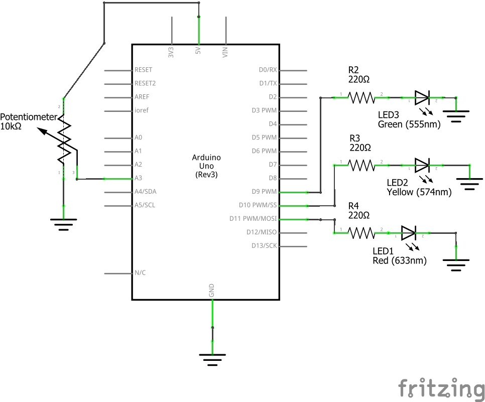
Now, send a wire from one of the digital pulse width modulation (PWM) outputs to your resistor/LED circuit. I sent three individual PWM outputs to three separate resistor/LED circuits to control different colored LEDs: green, yellow, and red. About 200-ohms resistance in series with the LED limits the current to the LED as a form of "protection" (remembering Ohm's Law, an increase in resistance while a voltage is held constant will drop the current). Below, you can toggle between a view of the Arduino output ports and a view of the LED circuit connections.
1 / 2 • Output ports: Red wire to red LED circuit, Orange-ish wire to the yellow-ish LED circuit, and the green wire to the green LED circuit.
Moving to the code, beyond variable initializations and IO definitions, I expanded on the example I found in the analogWrite() documentation with a conditional if/else statement such that the analogWrite() function would write to a different PWM output depending on the captured ADC value. Lower voltages were sent to the green LED, higher voltages sent to the yellow LED, and the upper range of voltages set to the red LED. Basically, I wanted to mimic audio level indicators that respond dynamically to audio levels. Red corresponds to a clipping signal (too much coming through), yellow is a warning that the signal is close to clipping, and green is in the safe zone. However, the PWM output resolution is one-fourth that of the ADC, so every time I used the ADC captured value variable I always divided it by 4, essentially scaling the ADC value to conform to the PWM resolution. This is why the 5V supply worked better for me. When I used the 3.3V supply, the results were not as desirable. Try it for yourself and see how the circuit responds.
Uploading the code onto the Arduino, you can now turn the potentiometer to vary the input voltage. You will find that as you decrease the resistance, more voltage is sent into the ADC and the PWM outputs will change from the green to yellow to red LEDs, respectively. Below, you can toggle between views of each LED lit up from adjusting the potentiometer.
1 / 3 • Green light: low voltage signal.
This was a fun introduction to coding with the Arduino but the tip of the iceberg for what is about to come. Stay tuned!


_ztBMuBhMHo.jpg?auto=compress%2Cformat&w=48&h=48&fit=fill&bg=ffffff)


Comments