

Hardware components | ||||||
 |
| × | 1 | |||
| × | 1 | ||||
 |
| × | 2 | |||
| × | 2 | ||||
| × | 2 | ||||
 |
| × | 3 | |||
| × | 1 | ||||
| × | 1 | ||||
| × | 1 | ||||
| × | 2 | ||||
| × | 1 | ||||
| × | 1 | ||||
 |
| × | 1 | |||
| × | 1 | ||||
 |
| × | 1 | |||
| × | 1 | ||||
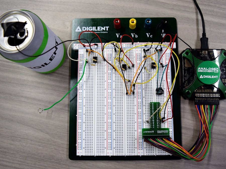
The theremin was the first electronic instrument, invented in 1920 by Russian physicist Lev Sergeyevich Termen as a product of the Soviet government's research into proximity sensors and originally called the etherphone. Known in the West as Leon Theremin, he moved to the United States and patented his invention in 1928. The theremin became a popular addition to radio programs and movies due to it's eerie sound. This project is an opportunity to build a theremin for a relatively low cost, learn a little about signal processing, and make some awesome noises!
I will go into detail about each stage of the circuit's instrumentation and behavior, but if you would like to just get going on your own I have provided schematics and an example of how the circuit might look when connected on a breadboard. These are downloadable and located at the end of the project.
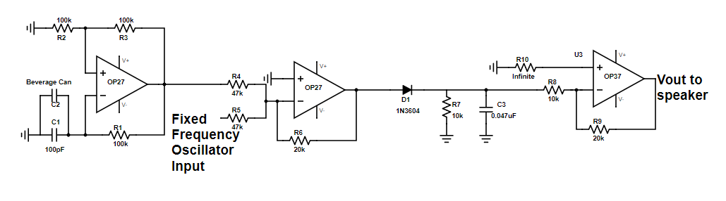
Theory of the CircuitThe way I think about this circuit is in six parts:
1. Variable-Frequency Oscillator
2. Fixed-Frequency Oscillator
3. Signal Mixer (Summing Amplifier)
4. Envelope Detector
5. Small Gain Amplifier
6. Speaker
The Variable-Frequency Oscillator and the Fixed-Frequency Oscillator signals are added together in the Signal Mixer, passed through the Envelope Detector, then amplified before being sent to a speaker. I will go through each of these stages, provide some explanation and theory of what is happening and why at each stage, and how to connect each stage's elements together. You can build each part separately and connect them at the end if you wish, although that may introduce more room for error. The output for one stage will be the input for the next.
OP27/37 PinoutBoth op amps used in this project have the same pin-out as presented in the following diagram. I will refer to the numbers associated with each pin in this diagram when describing circuit instrumentation. Identify the pins by locating the recessed semi-circle at the edge of the chip. I like to think about the pin numbers as increasing counter-clockwise from the "top-left". For further information about these op amps, refer to their respective data sheets. A link to each data sheet is provide in the materials list but are also available here:
http://www.analog.com/media/en/technical-documentation/data-sheets/OP27.pdf
http://www.analog.com/media/en/technical-documentation/data-sheets/OP37.pdf
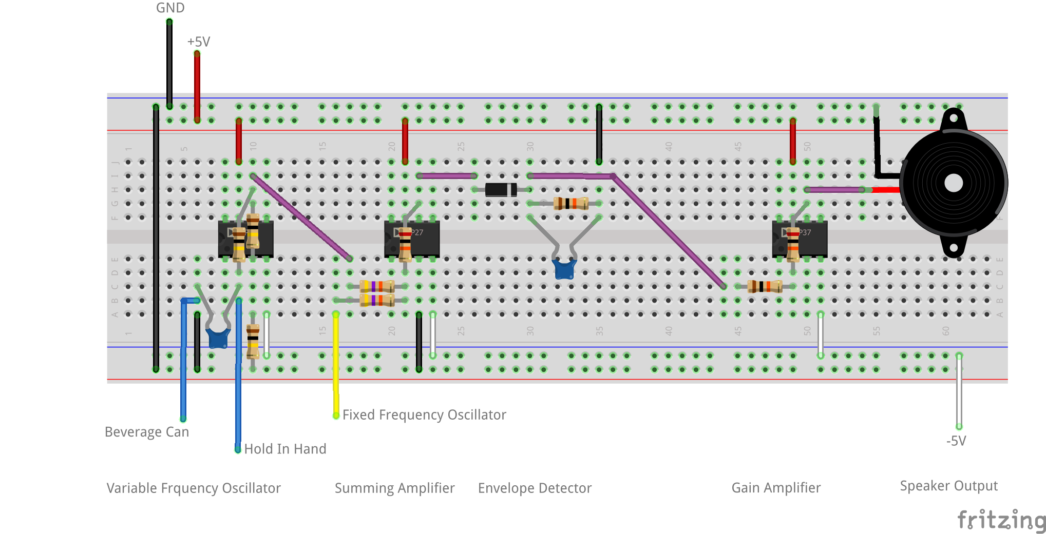
Schematic and breadboard diagrams (click the arrows to toggle images):
This part of the circuit is really the heart of our theremin. Connect the circuit as shown where the +in is pin 3, -in is pin 2, output is pin 6, V- is pin 4 (-5V), and V+ is pin 7 (+5V). That will remain the same for each op amp in this build. Connect a wire to each node about C1. One will be attached to your beverage can and one will be held in your hand during operation. This forms our parallel capacitance that will change the frequency of this stage's output. Vout for this stage will be one of the inputs to the Signal Mixer stage.
It usually helps to place op amps on the breadboard such that it straddles the center valley. That is not how the circuit is displayed in the breadboard diagram I provided, but may allow you more room on your breadboard to make connections at each pin of the op amp.
- R1 (100k ohm) connects pin 2 to pin 6 (feedback loop from output to input)
- R2 (100k ohm) connects pin 3 to ground
- R3 (100k ohm) connects pin 3 to pin 6
- C1 (100pF) connects pin 3 to ground
- C2 (wires and beverage can) is parallel to C1. Connect wires to each node about C1.
- V+ = +5 volts, V- = -5 volts (from Analog Discovery 2)
- Connect a ground wire from the Analog Discovery 2 to a node or rail such that it can be used for multiple grounding points.
Below is a couple pictures of how I hooked up the wires for the beverage can and your hand. One picture shows a closeup of the parallel connection to the fixed capacitor and another picture showing how I held and connected the wires (click the arrows to toggle images):
Note: The resistor and capacitor values are chosen for a 50% duty cycle and an output frequency in the range of about 20kHz to 28kHz (when one wire for variable capacitance is held), respectively. Changes to these RC values will change the duty cycle and astable output frequency.
After connecting the elements as shown, you need to use the Oscilloscope on the Analog Discovery 2 to determine the output frequency WHILE HOLDING THE WIRE THAT WILL BE HELD DURING THEREMIN OPERATION. The frequency of the output will be different if you do not hold the wire. You also need to keep your other hand a reasonable distance away from the beverage can as that will affect the measurement. We want to know the frequency while holding the wire because that will be the fundamental frequency (or baseband signal) during operation. The Fixed-Frequency Oscillator in the next step needs to be tuned to as close to this signal as possible. Also, make sure you turn on the power supplies in WaveForms for your op amp.
Below is a screen shot from WaveForms measuring the frequency of the output from the Variable-Frequency Oscillator. Remember, this is taken with one hand holding one of the wires used for the "beverage can capacitor". Without holding that wire, the frequency was higher, about 36kHz. Holding the wire, I measured a frequency of about 22.76kHz. This is the frequency I would use for my Fixed-Frequency Oscillator. Your frequency my not be exactly this value but within the mentioned range. Note: use the "Single" run button rather than the continuous "Run" button to capture a static value for the measured frequency.
So, what's going on here? This part of the circuit fascinated me while putting this project together as I had never worked with oscillators previously and I'm a sound nerd. After some research, what I have come to understand is that natural, environmental "noise" and non-ideal behavior of the circuit elements (namely C1) causes one of the plates of C1 to charge towards one of the power supply rails (the + or - 5 volt supplies). When the charge on C1 approaches the full value of the power supply, this causes transistors in the op amp to turn on/off, changing the signal path. Once this change occurs, the capacitor starts to discharge then charge towards the other power supply. Just as before, once the capacitor approaches the full value of the other power supply, transistors in the op amp turn on/off, changing the signal path and causing the capacitor to charge again towards the previous power supply. This will continue as long as the DC power is supplied to the op amp.
That is the best that I can explain what I have found on this behavior. I invite readers to comment, share, and correct me in the comments with anything you may know, find, or disagree with. The technical title for the circuit without the variable capacitance created with your hand and the beverage can is called an Astable Multivibrator. Implementing the variable capacitance, this portion of the circuit can be called a Variable-Frequency Oscillator. Super rad, right? I thought so.
Below is another screen shot from the Analog Discovery 2 Oscilloscope showing the voltage across the capacitor on channel 1 and the output voltage on channel 2:
This stage of the circuit will be implemented using the Wave Generator on the Analog Discovery 2. However, this can also be implemented with an astable multivibrator like in the Variable-Frequency Oscillator stage, which would essentially be a copy of that circuit without the beverage can capacitance. In WaveForms, set the Wave Generator to a sine wave (or try other alternating waveforms and listen to how it changes the output signal) of the same amplitude and frequency measured from the Variable-Frequency Oscillator stage. If you choose to build a discrete circuit for this stage, you will have to tune the output to the frequency measured from the Variable-Frequency Oscillator stage. That will involve changing the fixed capacitor value to adjust the frequency and would be best done with an oscilloscope to verify your results.
Below is a screen shot from WaveForms that shows the setup for the Fixed-Frequency Oscillator with a frequency and amplitude close to what was measured from the Variable-Frequency Oscillator.
Why implement another oscillator? Why tune it to the Variable-Frequency Oscillator output? We want two input signals that are as identical as possible because the output signal will actually be from what is called the "envelope" of the sum of the two signals. More on envelopes in that stage's description. In short (pun intended), the output will be a wave that is the outline of the summed signals amplitudes. That way, when the two signals are the same (no change in capacitance from the beverage can capacitor), there will be little to no output signal, i.e. no sounds when you're not trying to make any. I have included graphical examples of this with the Envelope Detector description.
Signal MixerSchematic and bread board diagrams (click the arrows to toggle images):
The input voltages to this stage are the output from the Variable-Frequency Oscillator and the signal from the Wave Generator on the Analog Discovery 2 (or a discrete astable multivibrator). It does not matter which signal is connected as Vin1 and Vin2. Connect the circuit as shown where the +in is pin 3, -in is pin 2, output is pin 6, V- is pin 4 (-5V), and V+ is pin 7 (+5V). That will remain the same for each op amp in this build. Note: the gain of this stage is the ratio of R6 to the parallel equivalent resistance of R4 and R5, which is close to 1 (also called unity gain).
- R4 (47k ohm) connects one input signal to pin 2
- R5 (47k ohm) connects the other input signal to pin 2
- Note: be sure that each input voltage is connected to separate nodes before connection to their resistors, then connect the resistors to the pin 2 node.
- R6 (20k ohm) connects pin 2 to pin 6 (feedback loop from output to input)
- V+ = +5 volts, V- = -5 volts (from Analog Discovery 2)
- Connect pin 3 to ground
This Signal Mixer stage of the circuit is called a "summing amplifier" because it amplifies the sum of the input signals. The input voltages converge to a single node and become a single signal. If the signals are close to identical, the result is simply a signal very similar in behavior with increased amplitude. If the signals have different frequencies, their sum will be a different looking waveform.
Examples of sums of AC signals are shown below using Desmos, a free online graphing calculator (click the arrows to toggle images):
Notice that the sum of dissimilar signals (different frequencies in this case) still has a periodic behavior because both original signals were periodic. To me, it kind of looks like one big wave made from a bunch of smaller waves. If you want to explore other examples, visit Desmos at https://www.desmos.com/calculator.
Here is a screen shot from WaveForms showing the summed signal from my circuit's oscillators:
Schematic and bread board diagrams (click the arrows to toggle images):
The Envelope Detector stage is only one diode, one resistor, and one capacitor. Vin is the summing amplifier's output signal and Vout goes to the next stage (small gain amplifier). Note: R7 and C3 can be interchanged such that C3 comes "first" from the diode.
- D1 (1N3604) connects Vin to Vout
- R7 (10k ohms) connects Vout to ground
- C3 (0.047uF) connects Vout to ground
The diode performs what is called "have-wave rectification" which allows only positive voltages (above the diode's threshold voltage) to pass, blocking negative voltages. This incoming increasing signal charges the capacitor until peak voltage, then the capacitor discharges through the resistor while the incoming signal drops in voltage. The capacitor discharges much slower than the frequency of the incoming signal allowing the output to follow the peaks of the input signal. The resistor and capacitor are together a low-pass filter, providing the voltage reference for Vout and some filtering to smooth out the result. This technique is also used in AM radio signals as demodulation for retrieving baseband signals. Because the peaks are changing in amplitude, the envelope will be a periodic representation of that change in peak amplitude. If the amplitude peaks are not changing, the envelope would be a straight line which would not produce a sound (no frequency, or DC).
Graphical examples using Desmos are shown below to illustrate the envelope of a mixed signal and "pure" signal (click the arrows to toggle images):
We now have our signal but it will benefit from some amplification as it is rather small and has a DC offset that will be corrected in the gain amplification stage.
Here is a screenshot of my measured envelope signal:
Schematic and breadboard diagrams (click the arrows to toggle images):
The input voltage is the output from the Envelope Detector stage. The output voltage will be sent to the speaker. Connect the circuit as shown where the +in is pin 3, -in is pin 2, output is pin 6, V- is pin 4 (-5V), and V+ is pin 7 (+5V). That will remain the same for each op amp in this build.
- R8 (10k ohms) connects the input signal to pin 2
- R9 (20k ohms) connects pin 2 to pin 6 (feedback loop from output to input)
- R10 is not a real resistor, leave pin 3 disconnected to anything. This simulates infinite resistance with an open circuit.
Pin 3 would normally be connected to ground via a very large resistor. As high of input resistance as possible is ideal for this amplifier for maximum voltage swing at the output which is why we are doing it this way. No current flow approximates infinite resistance.
Below is a screen shot of the final output signal from my circuit. Notice the correction of the DC offset and the inversion from the input. The effects of noise are compounded through this process and can be seen here as well. But it works!
This is the last stage, the stage where you get to hear what is happening from your hands and beverage can! Speakers have an input lead (red in the diagram) and a ground lead (black in the diagram).
- Connect Vout from the small gain amplifier to the positive lead of the speaker
- Connect the negative lead of the speaker to ground
My output is a little distorted from noise and lacks low end from using a tiny speaker. This output may sound better if you send it to a small instrument amplifier, like a guitar practice amp. This circuit is also very sensitive to environmental noise, especially laptop power supplies. Try to give yourself some decent space from any kind of power supply when operating your theremin for better sound results.
Final Thoughts/ResourcesAlthough the Analog Discovery 2 does have a price tag, it's cost is extremely lower than purchasing the lab equipment it would take to do the same work. The other benefit is that the Analog Discovery 2 can be used for many more projects and applications than is mentioned here.
This project was adapted and expanded from a previous Digilent project post that can be found here:
http://www.instructables.com/id/Theremin-Using-a-Soda-Can-and-the-Digilent-Analog-/#step0
Here is a short video that I thought was interesting and informative about how a theremin works:
Here is another resource about Summing Amplifiers from Digilent's Real Analog online circuits course: https://reference.digilentinc.com/_media/learn/courses/real-analog-chapter-5/lab5p4p2.pdf
When I read the original post, I had many questions and felt like a more thorough description of this project was necessary for those who wish to understand more about what is happening with this circuit. I also wanted to adapt the project presentation to reflect comments and concerns from the original post.
Please let me know what you think, what works/doesn't work, what I can improve on, what you learned from this, what you want to learn from this but did not, and any other comments you may have! Thanks!
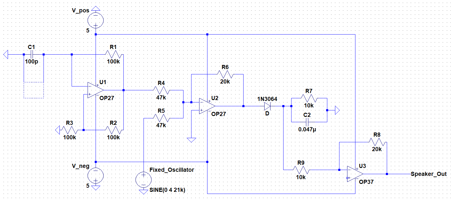
LT SPICE Schematic

Scheme-It Schemetic
Note: voltage sources to op amps need to be +/- 5 volts.
Breadboard Diagram


Comments