


Hardware components | ||||||
 |
| × | 1 | |||
| × | 1 | ||||
| × | 1 | ||||
| × | 1 | ||||
| × | 1 | ||||
Software apps and online services | ||||||
_4YUDWziWQ8.png?auto=compress%2Cformat&w=48&h=48&fit=fill&bg=ffffff) |
| |||||
| ||||||
 |
| |||||
Hand tools and fabrication machines | ||||||
 |
| |||||
| ||||||
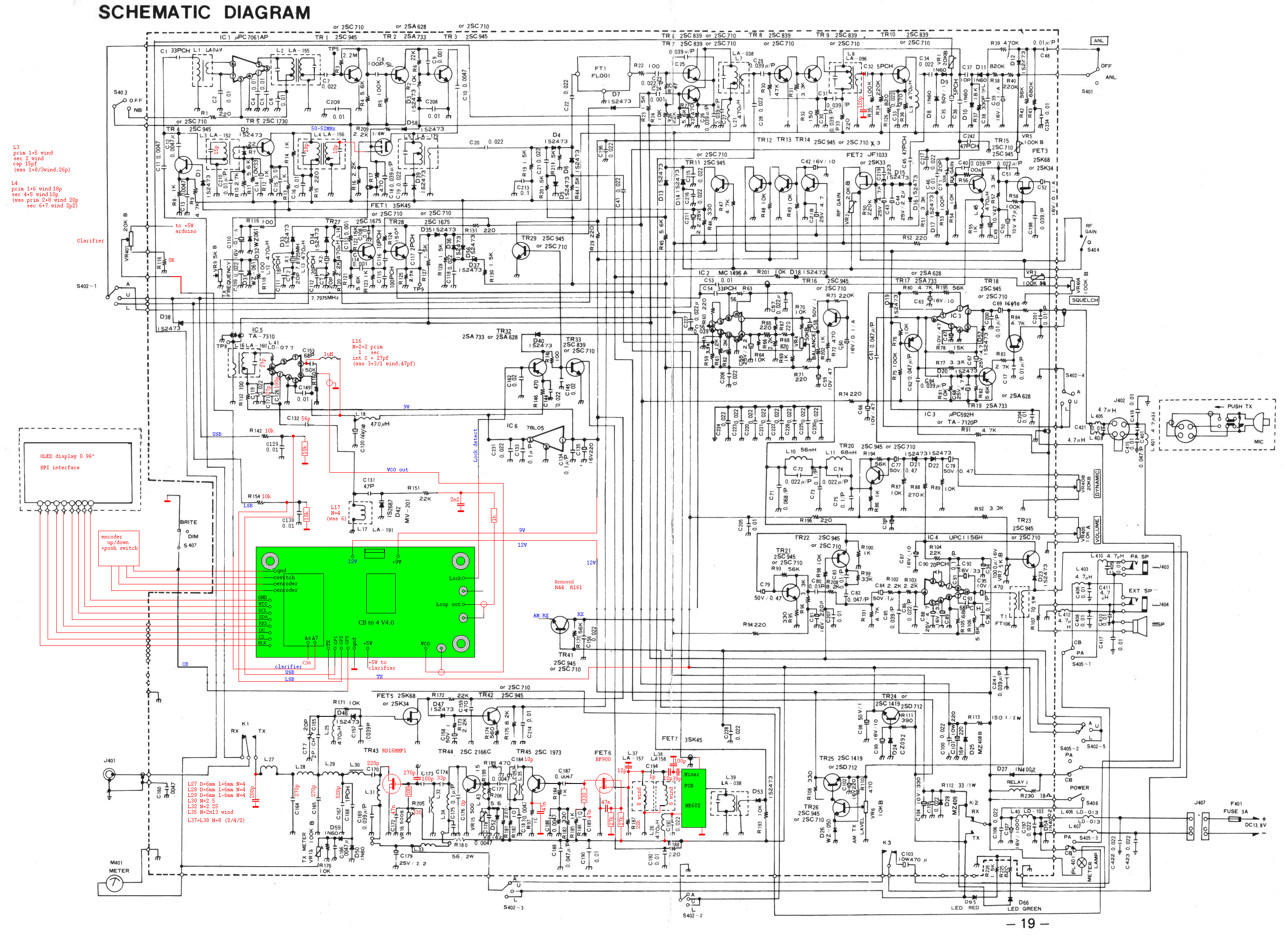
I have choosen this CB transceiver because it can not be used here in the Netherlands legally on 27MHz. There is no FM in it and originally it has only 40 channels. There are other brands like Palomar, Universe and President that use the same PCB with 7.8MHz IF, which can also be used.
For this project, I designed a PCB on which there is an Arduino, DDS and a PLL. The PCB is connected to a Color TFT display, encoder with switch, a potmeter, and to the CB transceiver.
In an earlier stage i used an OLED display, but these show burn-in effects after a year so i have upgraded the display to a color TFT display.
In the CB transceiver the PLL, reference oscillators, display and channel switch are removed and their function is take over by the PCB.
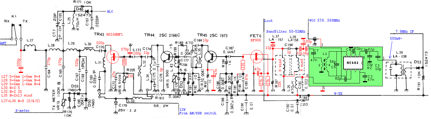
The RF circuits of receiving part and the transmitting part that are tuned to 27MHz are changed to 50MHz. This hardest part of the project was to solve oscillation of the transmitter by adding sufficient decoupling, shielding and grounding.
The Arduino has some inputs: - encoder with switch -clarifier potmeter - USB, lsb mode and transmit.
The Arduino has some outputs to: -TFT display -PLL - DDS
The VCO in the transceiver can be tuned from 57.8MHz to 59.8MHz. This is 7.8MHz (Intermediate frequency of the transceiver) above the actual working frequency of 50 to 52MHz. The VCO frequency is divided by a factor 588 in the PLL. The phase comparitor of the PLL works at about 100kHz. That is also the frequency the DDS makes. The DDS makes the reference frequency of the PLL. This way a very small frequency grid of 10Hz can be used. This is very conveinient when working in SSB.
The clarifier potmeter is in the original design connected to a reference oscillator. This oscillator is removed and the botmeter is connected to an analog input (A7) of the arduino. The receiving frequency can be changed + and - 512 Hz by tuning the clarifier. During transmitting it is disabled in the software.
In the next block diagram i hope to make things more clear:
Picture with the channel switch and display removed:
Now added an OLED display and encoder switch:
And how the firmware is uploaded to the transceiver:
A film of how the actual transceiver is working at 50MHz (the display is upgraded to the color display later):
And it does not only work on 50MHz , but i have been able to add the PCB to a MAJOR M588 which is converted to the 70MHz band. This band is only legal in Europe as far as i know.
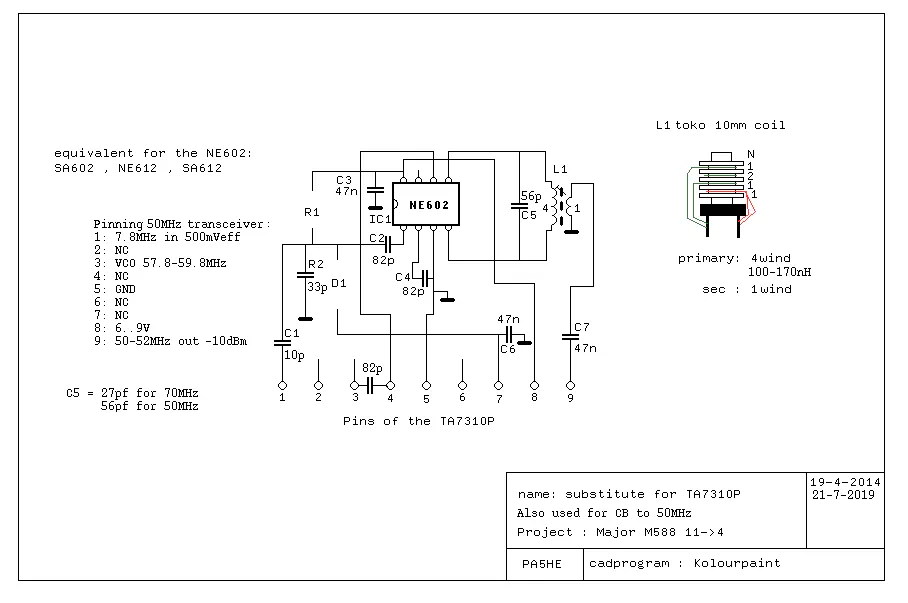
Mixer 7.8 to 50...52MHz

50MHz_OLED_PLL_DDS
ArduinoIt reads an encoder switch and sends data to an TFT display , PLL and DDS
/* Firmware for CB transceiver with Uniden main board
This firmware is intended for the 6 meter amateurband
The hardware needed can be build on PCB V4.0
This hardware consists of an Arduino Pro mini ,TFT Display 240x135, AD9833 and MC145170
A dedicated header file FreeSans24pt7b_numbers.h is created to preserve memory-space
 */
#include <Arduino.h>
#include <Adafruit_ST7789.h>
#include <EEPROM.h>
#include <Fonts/FreeSans12pt7b.h>
//#include "FreeSans24pt7b_numbers.h"
#include<avr/io.h>                   // AVR/IO.H header file

#define pulseLow(pin) {digitalWrite(pin, LOW); digitalWrite(pin, HIGH); }
#define TFT_CS 10
#define TFT_DC 7
#define TFT_RST 6    //pin not used
Adafruit_ST7789 tft = Adafruit_ST7789(TFT_CS, TFT_DC, TFT_RST);
#define lowerborder 49000000                  //lowest frequency  49MHz
#define upperborder 53000000                  //highest frequency 53MHz

#define encoderPin1 2            // encoder
#define encoderPin2 3            // encoder
int switchcontact= 4;            // connect USB pin to D4
#define blk_pin 5                // backlight pin low is off , high is on
// pin D6 is used for TFT display
// pin D7 is used for TFT display
#define GP1  8                   // USB
#define txpin 9                  // assign tx to D9
// pin D10 is used  TFT display
// pin D11 is used Serial data of the hardware SPI bus
#define enableSPI  12            // not used
// pin D13 is used for Serial clock of the hardware SPI bus
#define GP2 14                   // LSB
#define DDS_Fsync 15             // pin D15 or A1 enable pin of the DDS
#define PLL_enb  16              // pin D16 or A2 PLL enable
#define GP3 17                   // pin D17 or A3 assigned to scanmode if high = normal , if connected to ground = scanmode
#define rssi_pin A6              // connect this pin to the RSSI of the radio
#define clarifier A7             // connect this to the calrifier potmeter (0...5V)
volatile int lastEncoded = 0;    // encoder
long lastencoderValue = 0;       // encoder
int lastMSB = 0;                 // encoder
int lastLSB = 0;                 // encoder
int encoderValue = 0;            // encoder
uint32_t rx=50150000;             // Starting frequency of VFO in 1Hz steps
uint32_t rx2=1;                  // variable to hold the updated frequency
uint32_t increment = 10000;      // starting VFO update increment in 10kHZ.
int buttonstate = 0;             // if the button is pressed or not
int memstatus = 1;               // value to notify if memory is current or old. 0=old, 1=current.
int_fast32_t timepassed = millis(); // int to hold the arduino millis since startup
uint32_t startTime=0;
int offset=0;                    // frequency error in Hz can be corrected here
int mode, oldmode,duration,oldpotmeterValue =0;
uint16_t main_number_color=ST77XX_YELLOW;
uint16_t SelectNumberColor=ST77XX_RED;
byte save_showFreq[9]={10,10,10,10,10,10,10,10,10};
byte shiftchanged,shortpress,longpress=0,keypress=0,resetpress,Operating_mode,endpress,oldcounter,scan,clearscreenScanfrequency,lsb,usb=0;
int ctcss_counter2,preset,preset2=0;

void setup(void) {
  ADCSRA = 0xC7;               //adc enabled , start adc , set prescaler 128
  ADCSRB = 0x00;               //adc free running mode
  pinMode(blk_pin, OUTPUT);
  digitalWrite(blk_pin,HIGH);                //backlight on
  tft.init(135,240);
  tft.setRotation(3);
  tft.invertDisplay(1);
  tft.fillScreen(ST77XX_BLACK);
  tft.setTextColor(ST77XX_GREEN);
  firsttimeIncrementLine();
  pinMode(encoderPin1, INPUT_PULLUP);
  pinMode(encoderPin2, INPUT_PULLUP);
  pinMode(switchcontact,INPUT_PULLUP);       // Connect to a button that goes to GND on push
  pinMode(GP1,INPUT_PULLUP);
  pinMode(txpin,INPUT);
  pinMode(GP2,INPUT_PULLUP);
  pinMode(DDS_Fsync, OUTPUT);
  pinMode(PLL_enb, OUTPUT);                  // All pins connected to the PLL are outputs
  pinMode(GP3,INPUT_PULLUP);                 //cal only be input bacause the HW SPI bus controls this pin.
  attachInterrupt(0, updateEncoder, CHANGE); //interrupt connected to the encoder
  attachInterrupt(1, updateEncoder, CHANGE);
  resetPLL();
  setupDDS();
  setupPLL();                 //set the PLL
  EEPROM.get(0,rx);                          //read the last frequency from memory
  if (rx >=upperborder){rx=50150000;};       // fallback in case there is something wrong in the memory
  if (rx <=lowerborder){rx=50150000;};
  //MemoryDataSize=3;
  Serial.begin(9600);  //for debugging
 // Serial.print(MemoryDataSize);Serial.print(" ");
  //                  Serial.print(increment); // DEBUG
     Serial.print("\n");
}
void loop(void) {
    byte lsb=digitalRead(GP2);
    byte usb=digitalRead(GP1);
    byte tx=digitalRead(txpin);
    scan = digitalRead(GP3);
    mode=lsb+usb+tx+scan;
    int frequencyerror = 127-512;                   // add here the frequencyerror at 50MHz in Hz 512 is the offset from the clarifierpotmeter
    int offset=0;                                   //has to do with the 7.8MHz IF of the Palomar
    int potmeterValue=analogRead(clarifier);                          //read potmeter connected to pin 7 10bits ADC 0....1024
        if (!scan&!tx) {scanfrequency(rx);}
        else{
           if ((mode!=oldmode)||(potmeterValue!=oldpotmeterValue)){
                  if (tx){ offset=frequencyerror+2902-(lsb*5128);}
                    else {offset=frequencyerror+(usb*2390)-(lsb*2738)+potmeterValue;} //tx switches the clarifier off
             sendFrequency(rx+offset,tx,0);
           }
           if ((rx != rx2)||(mode!=oldmode)){    //determine if something has changed
              if (rx >=upperborder){rx=upperborder;};                                 // UPPER VFO LIMIT
              if (rx <=lowerborder){rx=lowerborder;};                                 // LOWER VFO LIMIT
              if (tx){ offset=frequencyerror+2902-(lsb*5128);}
                    else {offset=frequencyerror+(usb*2390)-(lsb*2738)+potmeterValue;} //tx switches the clarifier off
              sendFrequency(rx+offset,tx,0);                                          // frequency is send to the DDS
              showFreq(rx);                                                          //frequency is send to the display
              Serial.print(rx);Serial.print(" ");Serial.print(rx2);Serial.print(" ");Serial.print(potmeterValue);Serial.print("\n");
              rx2 = rx;                                                               //remenber for the next time in the loop
              if (rx2 >=upperborder){rx2=upperborder;};                               // Correction in case there have been 2 interrupts
              if (rx2 <=lowerborder){rx2=lowerborder;};
              }
          }
   buttonstate = digitalRead(switchcontact);                // read button
   oldmode=mode;
   oldpotmeterValue=potmeterValue;
   if(buttonstate == LOW) { setincrement(); };
   if(memstatus == 0){                                      // Write the frequency to memory if not stored and 2 seconds have passed since the last frequency change.
      if(timepassed+2000 < millis()){ storeMEM(); }
      }
}
void firsttimeIncrementLine(){
 byte y_pos=68;
tft.fillRect(120,y_pos, 22,4, SelectNumberColor);
                             }

void setincrement(){
  byte y_pos=68;
  if(increment == 10){increment = 100000;               tft.fillRect(220,y_pos, 50,4, ST77XX_BLACK) ;tft.fillRect(85,y_pos, 22,4, SelectNumberColor); }
  else if (increment == 100000){increment = 10000;      tft.fillRect(85,y_pos, 22,4, ST77XX_BLACK)  ;tft.fillRect(120,y_pos, 22,4, SelectNumberColor); }
  else if (increment == 10000){increment = 1000;        tft.fillRect(120,y_pos, 22,4, ST77XX_BLACK)  ;tft.fillRect(155,y_pos, 22,4, SelectNumberColor);}
  else if (increment==1000) {increment = 100;           tft.fillRect(155,y_pos, 22,4, ST77XX_BLACK) ;tft.fillRect(190,y_pos, 16,4, SelectNumberColor);}
  else if (increment==100) {increment = 10;             tft.fillRect(190,y_pos, 22,4, ST77XX_BLACK) ;tft.fillRect(220,y_pos, 16,4, SelectNumberColor);}
  //showFreq(rx);
  delay(200);   // added delay to get a more smooth reaction of the push button
}

void updateEncoder(){
int MSB = digitalRead(encoderPin1);        //MSB = most significant bit
int LSB = digitalRead(encoderPin2);         //LSB = least significant bit
int encoded = (MSB << 1) |LSB;             //converting the 2 pin value to single number
int sum = (lastEncoded << 2) | encoded;    //adding it to the previous encoded value
if(sum == 0b1101 || sum == 0b0100 || sum == 0b0010 || sum == 0b1011) encoderValue ++;
if(sum == 0b1110 || sum == 0b0111 || sum == 0b0001 || sum == 0b1000) encoderValue --;
if(encoderValue == 4) {rx-=increment ; encoderValue=0;} // there are 4 changes between one click of the encoder
if(encoderValue == -4) {rx+=increment ; encoderValue=0;}   // it can be neccessary to reduce these to 2 for other encoders
lastEncoded = encoded;
}

void showFreq(uint32_t local_freq){     //   0 frequency     1 frequencystep
   byte tenmillions =((local_freq/10000000)%10);     //1000kHz
   byte millions = ((local_freq/1000000)%10);     //1000kHz
   byte hundredk = ((local_freq/100000)%10);     //100kHz
   byte tenk =     ((local_freq/10000)%10);      //10kHz
   byte onek =     ((local_freq/1000)%10);       //1kHz
   byte hundreds = ((local_freq/100)%10);        //100Hz
   byte tens =     ((local_freq/10)%10);         //10Hz
   if(clearscreenScanfrequency==0){tft.fillScreen(ST77XX_BLACK);setincrement();}
   clearscreenScanfrequency=1;
   int bandplan=rx/1000-50000;
   byte bandplan_var;
   if (tenmillions!=save_showFreq[2]){draw7Number(tenmillions, 5, 1, 3,main_number_color,ST77XX_BLACK, 1);}
   if (millions!=   save_showFreq[3]){draw7Number(millions,   40, 1, 3,main_number_color,ST77XX_BLACK, 1);}
   if (hundredk!=   save_showFreq[4]){draw7Number(hundredk,   85, 1, 3,main_number_color,ST77XX_BLACK, 1);}
   if (tenk!=       save_showFreq[5]){draw7Number(tenk,      120, 1, 3,main_number_color,ST77XX_BLACK, 1);}
   if (onek!=       save_showFreq[6]){draw7Number(onek,      155, 1, 3,main_number_color,ST77XX_BLACK, 1);}
   if (hundreds!=   save_showFreq[7]){draw7Number(hundreds,  190,20, 2,main_number_color,ST77XX_BLACK, 1);}
   if (tens!=       save_showFreq[8]){draw7Number(tens,      210,20, 2,main_number_color,ST77XX_BLACK, 1);}
    tft.setFont(&FreeSans12pt7b);// tft.setTextSize(1);
    char *band_usage[]={"","Digi mode","Beacons","Phone SSB","Data","Sat","Repeater in","Repeater out","CTCSS","SSB Call","SSTV","FAX","RTTY","Wspr","out of band","RH7 out","RH8 out","FM call","Phone FM","CW","RH1 in","RH2 in","RH3 in","RH4 in","RH1 out","RH2 out","RH3 out","RH4 out"};
      //0="" 1="Digi mode" 2="Beacons" 3="Phone SSB" 4="Data" 5="Sat" 6="Repeater in" 7="Repeater out" 8="CTCSS",9="SSB Call",10="SSTV",11="FAX",12="RTTY",13="Wspr","out of band","RH7 out","RH8 out","FM call","Phone FM","CW","RH1 in","RH2 in","RH3 in","RH4 in","RH1 out","RH2 out","RH3 out","RH4 out"
         bandplan_var=0;                                        //default
         if (bandplan<0)                    {bandplan_var=14;}
         if (bandplan>=0&&bandplan<100)     {bandplan_var=19;}  //CW
         if (bandplan>=100&&bandplan<500)   {bandplan_var=3 ;}  //Phone SSB
         if (bandplan>=500&&bandplan<2000)  {bandplan_var=18;}  //Phone FM
         if (bandplan>=1210&&bandplan<1390) {bandplan_var=6 ;}  //Repeater in
         if (bandplan>=1810&&bandplan<1990) {bandplan_var=7 ;}  //repeater out
         if (bandplan==150)                 {bandplan_var=9 ;}  //SSB call
         if (bandplan==400)                 {bandplan_var=13;}  //Wspr
         if (bandplan==510)                 {bandplan_var=10;}  //SSTV
         if (bandplan==550)                 {bandplan_var=11;}  //FAX
         if (bandplan==600)                 {bandplan_var=12;}  //RTTY
         if (bandplan==1510)                {bandplan_var=17;}  //FM Call
         if (bandplan>2000)                 {bandplan_var=14;}
      if (bandplan_var!=save_showFreq[1]) {tft.setTextColor(ST77XX_BLACK);tft.setCursor(10,110);tft.print(band_usage[save_showFreq[1]]);
                                           tft.setTextColor(ST77XX_GREEN);tft.setCursor(10,110);tft.print(band_usage[bandplan_var]);}
    timepassed = millis();
    memstatus = 0;           // Trigger memory write
    save_showFreq[1]=bandplan_var;
    save_showFreq[2]=tenmillions;
    save_showFreq[3]=millions;
    save_showFreq[4]=hundredk;
    save_showFreq[5]=tenk;
    save_showFreq[6]=onek;
    save_showFreq[7]=hundreds;
    save_showFreq[8]=tens;
    save_showFreq[0]=tens; //save values for the next time to write in black
                              }

void resetPLL(void){
  digitalWrite(PLL_enb, HIGH);
  SPI.beginTransaction(SPISettings(8000000, MSBFIRST, SPI_MODE0)); //RA2 enb RA0 clk RA1 dta
  SPI.transfer(0);
  digitalWrite(PLL_enb, LOW);
  SPI.transfer(0x10);
  digitalWrite(PLL_enb, HIGH);
  SPI.endTransaction();
}

void sendFrequency(long frequency, byte tx , int repeatershift) {                 // frequency in Hz , TX 0 or 1 , repeatershift in kHz
            frequency+=7800000;                                                   //add IF
            long freq = (float)frequency *268435456/962418820;                    // 16.367667 TCXO clock = 58.8*16367667= 962418820
             //    Serial.print(freq,DEC); // DEBUG
             //   Serial.print("\n");
            SPI.beginTransaction(SPISettings(8000000, MSBFIRST, SPI_MODE2));
            digitalWrite(DDS_Fsync, LOW);
            tfr_byte(0x2000);                     //control word
            digitalWrite(DDS_Fsync, HIGH);
            digitalWrite(DDS_Fsync, LOW);
            tfr_byte(0x4000|(freq & 0x3FFF)); //LSB first
            freq>>=14;
            tfr_byte(0x4000|(freq & 0x3FFF));  //MSB next
            digitalWrite(DDS_Fsync, HIGH);
            SPI.endTransaction();}

void tfr_byte(unsigned int data)  {                       // transfers 16 bits, MSB first to the 9833 via serial DDS_SDA line
             for (int i=0; i<2; i++, data<<=8){
             int spidata1=data;
             spidata1>>=8;
             byte spidata= (int8_t)spidata1;      //cast int to byte
             SPI.transfer(spidata);
             }
                                  }

void pllregister(unsigned int count, unsigned int bitsdata)  {      // transfers 16 bits, MSB first to the MC145170PLL
             SPI.beginTransaction(SPISettings(8000000, MSBFIRST, SPI_MODE0));
             digitalWrite(PLL_enb, LOW);
             if (count==1){byte spidata= (int8_t)bitsdata;
                           SPI.transfer(spidata);
                           }
             if (count==2){
                    for (int i=0; i<count; i++, bitsdata<<=8){
                        int spidata1=bitsdata;
                        spidata1>>=8;
                        byte spidata= (int8_t)spidata1;      //cast int to byte
                        SPI.transfer(spidata);
                                                   }
                           }
             if (count==3){
                    count--;
                    SPI.transfer(0);
                    for (int i=0; i<count; i++, bitsdata<<=8){
                        int spidata1=bitsdata;
                        spidata1>>=8;
                        byte spidata= (int8_t)spidata1;      //cast int to byte
                        SPI.transfer(spidata);                   }

                           }
                  digitalWrite(PLL_enb,HIGH);
                  SPI.endTransaction();
                                                             }


void setupDDS(){
  SPI.beginTransaction(SPISettings(8000000, MSBFIRST, SPI_MODE2));
   digitalWrite(DDS_Fsync, LOW);
  tfr_byte(0x100);      // reset DDS
   digitalWrite(DDS_Fsync, HIGH);
   digitalWrite(DDS_Fsync, LOW);
  tfr_byte(0x2000);    // set DDS 0x2020=block 0x2000=sine
   digitalWrite(DDS_Fsync, HIGH);
  SPI.endTransaction();
}

void setupPLL() {
     pllregister (1,0x70) ;                         //write C register (1 byte)  70hex
     pllregister (2,0x24C) ;                         //write N register(2 bytes) N=1588
     pllregister (3,10);                            //write R register (3 bytes) 10 = 100kHz
                }

void setup_display(){
  tft.fillScreen(ST77XX_BLACK);
  tft.setTextColor(ST77XX_GREEN);
  tft.setFont(&FreeSans12pt7b);
  tft.fillRect(81,45, 22,4, ST77XX_RED);
  draw7Number(2, 1, 1, 2,main_number_color,ST77XX_BLACK, 1);
  tft.fillCircle(49,40,3,main_number_color);
 // tft.setFont(&FreeSans24pt7b); // tft.setTextSize(2);
 // tft.setCursor(30, 36); tft.setTextColor(ST77XX_GREEN);tft.print(".");
  tft.setFont(&FreeSans12pt7b); //
}

   void storeMEM(){            //write the frequency to memory to remember the last frequency
   EEPROM.put(0,rx);
   memstatus = 1;          // Let program know memory has been written
}


/**********************************************************************************
 Routine to Draw Large 7-Segment formated number with Arduino TFT Library
    by William Zaggle  (Uses TFT Library DrawLine functions).
   int n - The number to be displayed
   int xLoc = The x location of the upper left corner of the number
   int yLoc = The y location of the upper left corner of the number
   int cSe = The size of the number. Range 1 to 10 uses Large Shaped Segments.
   fC is the foreground color of the number
   bC is the background color of the number (prevents having to clear previous space)
   nD is the number of digit spaces to occupy (must include space for minus sign for numbers < 0)
   nD < 0 Suppresses leading zero

   Sample Use: Fill the screen with a 2-digit number suppressing leading zero
          draw7Number(38,20,40,10,WHITE, BLACK, -2);
**********************************************************************************/
void draw7Number(int n, unsigned int xLoc, unsigned int yLoc, char cS, unsigned int fC, unsigned int bC, char nD) {
  unsigned int num=abs(n),i,s,t,w,col,h,a,b,si=0,j=1,d=0,S1=cS,S2=5*cS,S3=2*cS,S4=7*cS,x1=(S3/2)+1,x2=(2*S1)+S2+1,y1=yLoc+x1,y3=yLoc+(2*S1)+S4+1;
  unsigned int seg[7][3]={{(S3/2)+1,yLoc,1},{x2,y1,0},{x2,y3+x1,0},{x1,(2*y3)-yLoc,1},{0,y3+x1,0},{0,y1,0},{x1,y3,1}};
  unsigned char nums[12]={0x3F,0x06,0x5B,0x4F,0x66,0x6D,0x7D,0x07,0x7F,0x67,0x00,0x40},c=(c=abs(cS))>10?10:(c<1)?1:c,cnt=(cnt=abs(nD))>10?10:(cnt<1)?1:cnt;
  for (xLoc+=cnt*(d=(2*S1)+S2+(2*S3)+2);cnt>0;cnt--){
    for (i=(num>9)?num%10:((!cnt)&&(n<0))?11:((nD<0)&&(!num))?10:num,xLoc-=d,num/=10,j=0;j<7;++j){
      col=(nums[i]&(1<<j))?fC:bC;s=(2*S1)/S3;
      if (seg[j][2])for(w=S2,t=seg[j][1]+S3,h=seg[j][1]+(S3/2),a=xLoc+seg[j][0]+S1,b=seg[j][1];b<h;b++,a-=s,w+=(2*s))tft.drawFastHLine(a,b,w,col);
      else for(w=S4,t=xLoc+seg[j][0]+S3,h=xLoc+seg[j][0]+S3/2,b=xLoc+seg[j][0],a=seg[j][1]+S1;b<h;b++,a-=s,w+=(2*s))tft.drawFastVLine(b,a,w,col);
      for (;b<t;b++,a+=s,w-=(2*s))seg[j][2]?tft.drawFastHLine(a,b,w,col):tft.drawFastVLine(b,a,w,col);
    }
  }
}
void scanfrequency (long frequency){ //display 240x135
  if (clearscreenScanfrequency){tft.fillScreen(ST77XX_BLACK);clearscreenScanfrequency=0;for (int i=0;i<9;i++) save_showFreq[i]=10;tft.fillCircle(90,20,2,main_number_color);} //reset variables for showFreq
draw7Number(frequency/1000000, 60, 1, 1,main_number_color,ST77XX_BLACK, 2);
draw7Number((frequency/1000)%1000, 95, 1, 1,main_number_color,ST77XX_BLACK, 3);
  frequency-= 240000;  //start 240kHz lower, makes 120 steps of 2kHz
  //tft.setCursor(60, 12);tft.print(frequency/1000);
             for (int fstep=0;fstep<239;fstep++){
              //debug
              frequency +=2000;
            long freq = (float)(frequency+7800000) *268435456/962418820;  // 16.367667 TCXO clock = 58.8*16367667= 962418820
             //Serial.print(frequency);Serial.print(" ");Serial.print(fstep);Serial.print(" ");Serial.print(freq); Serial.print("\n");
            SPI.beginTransaction(SPISettings(8000000, MSBFIRST, SPI_MODE2));
            digitalWrite(DDS_Fsync, LOW);
            tfr_byte(0x2000);                     //control word
            digitalWrite(DDS_Fsync, HIGH);
            digitalWrite(DDS_Fsync, LOW);
            tfr_byte(0x4000|(freq & 0x3FFF)); //LSB first
            freq>>=14;
            tfr_byte(0x4000|(freq & 0x3FFF));  //MSB next
            digitalWrite(DDS_Fsync, HIGH);
            SPI.endTransaction();
            if (digitalRead(GP3) == HIGH) { fstep=239;  }   //end this mode fast
             int rssi= analogRead(rssi_pin)/9; if (rssi>=112){rssi=112;}
             _delay_ms(5);
             if (fstep==0){ tft.drawFastVLine(0,22,112,ST77XX_BLACK);}
             if (fstep<240){tft.drawFastVLine(fstep+1,22,112,ST77XX_BLACK);}    //erase line
             if (fstep<239){tft.drawFastVLine(fstep+2,22,112,ST77XX_BLACK);}    //erase line
              uint16_t VlineColor=ST77XX_GREEN;
             if (fstep==119||fstep==120||fstep==121){VlineColor=ST77XX_RED;}
             tft.drawFastVLine(fstep,134-rssi,rssi+1,VlineColor);
             }
}


_Ujn5WoVOOu.png?auto=compress%2Cformat&w=40&h=40&fit=fillmax&bg=fff&dpr=2)

_3u05Tpwasz.png?auto=compress%2Cformat&w=40&h=40&fit=fillmax&bg=fff&dpr=2)


Comments