



Hardware components | ||||||
| × | 1 | ||||
| × | 1 | ||||
| × | 1 | ||||
Software apps and online services | ||||||
 |
| |||||
OVERVIEW
This project turns the 1.91-inch LilyGO T-Display-S3 AMOLED into a compact environmental desk dashboard. The main page presents the current local time together with readings from an LTR390 UV/ambient-light sensor and a BH1750 lux sensor. Dedicated detail pages provide larger readings and rolling history graphs, while a fourth page shows Wi-Fi network and signal information.
The display uses a landscape “Nightlight” theme designed for the AMOLED panel. Pressing the BOOT button cycles through Summary, LTR390, BH1750, and Wi-Fi pages. On touch-enabled boards, the page button in the header can also be used.
The clock synchronizes over Wi-Fi using NTP. Timezone configuration uses a POSIX timezone string, with MYT-8 supplied for Malaysia.
FEATURES
• NTP-synchronized local clock and date
• LTR390 raw UV count, calculated UV index, and raw ALS reading
• Separate rolling graphs for LTR390 measurements
• BH1750 lux reading and full-width illuminance history
• Wi-Fi SSID, RSSI, strength meter, and signal history
• BOOT-button and optional touchscreen page navigation
• Landscape interface built with LVGL for the RM67162 AMOLED panel
WIRING
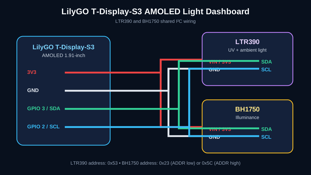
Both sensors share the same I2C bus:
• GPIO 3 → SDA on LTR390 and BH1750
• GPIO 2 → SCL on LTR390 and BH1750
• 3V3 → VIN/3V3 on both sensors
• GND → GND on both sensors
The LTR390 uses address 0x53. The BH1750 normally uses 0x23; set BH1750_ADDRESS to 0x5C if its ADDR pin is high.
SOFTWARE SETUP
The firmware is built with PlatformIO and the Arduino framework. It uses the official LilyGO AMOLED library, LVGL 8.4, Adafruit LTR390 Library 1.1.2, and BH1750 1.3.0.
1. Download the attached source archive.
2. Copy include/secrets.example.h to include/secrets.h.
3. Add your Wi-Fi SSID and password and confirm the POSIX timezone.
4. Connect the board over USB-C.
5. Build and upload the lilygo-amoled PlatformIO environment.
6. Open the serial monitor at 115200 baud for diagnostics.
The verified build uses approximately 14.7% of RAM and 36.1% of the configured application flash.
HOW IT WORKS
At startup, the ESP32-S3 initializes the RM67162 AMOLED panel and creates four LVGL pages. The two sensors share one I2C bus. The BH1750 remains in continuous high-resolution mode, while the LTR390 alternates between ambient-light and UV modes with a short settling interval between measurements. Each sample is normalized for its on-screen meter and appended to a 48-point rolling chart.
Wi-Fi reconnect logic runs without blocking the interface. Once connected, the ESP32 time service synchronizes against pool.ntp.org or time.nist.gov and applies the configured POSIX timezone. The LVGL timer continues to run while sensor, clock, button, and network updates are scheduled with millis().
TESTING
After uploading, the board successfully initializes the AMOLED display, connects to Wi-Fi, synchronizes the clock, and reads both I2C sensors. The Summary, LTR390, BH1750, and Wi-Fi pages can be cycled with the BOOT button.
TROUBLESHOOTING
• If uploading fails, use a data-capable USB-C cable. Hold BOOT, tap RESET, and retry to enter the ROM bootloader.
• If a sensor is offline, check 3.3 V, ground, SDA/SCL, and the selected BH1750 address.
• If the clock remains blank, check Wi-Fi credentials, internet access, and the timezone string.
• A blank or corrupted screen usually means the wrong LilyGO AMOLED model was selected; this firmware specifically targets the 1.91-inch board.
NOTES
This project targets the 1.91-inch LilyGO AMOLED model and calls beginAMOLED_191() explicitly. It requires an ESP32-S3 configuration with 16 MB flash and OPI PSRAM. Source code and documentation are released under the MIT License; dependencies retain their own licenses.


Comments