


Hardware components | ||||||
| × | 1 | ||||
Software apps and online services | ||||||
 |
| |||||
One day in a furniture shop I have seen a big, approx 60cm x 60cm, frame that displayed the actual time not by clock hand but by illuminated words, e.g. "It's five to twelve", "It's quarter past seven". I liked it! But there was one problem - my wife ;-) In her opinion the clock was too big and did not fit
to our housing style.
From that moment this project was born. Although several websites exist I preferred to build my own one fulfilling the following spec:
- Small size, fitting into a standard picture frame 13x18cm. This allows to choose your preferred frame style and color, ...
- Individual configurable illumination per word
- Adaptive brightness related to the ambient light
- Configurable daily Alarm setting
- Control by Smartphone (BLE, Bluetooth Low energy)
- Cost sensitive
- Easily reproducible for hobbyists
As main controller unit Cypress' PSoC 4 BLE Module CY8CKIT-142 was selected, as it is cheap and includes all required peripherals.
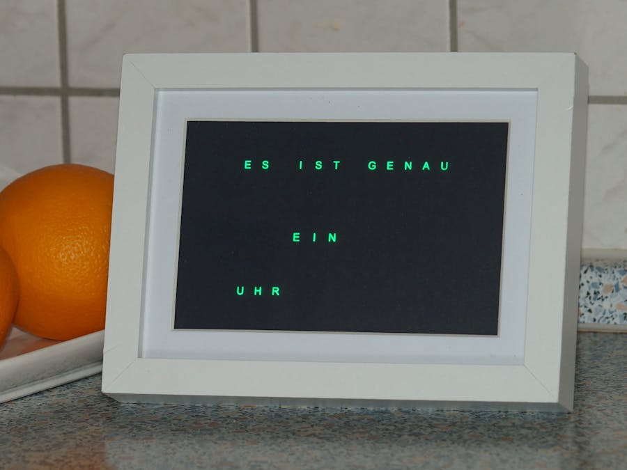
Note: Before you continue building your own CyWordClock: The following instructions will describe the clock word layout for GERMAN language: 11:55 = "ES IST FÜNF VOR ZWÖLF UHR", 7:15 = "ES IST FÜNFZEHN NACH SIEBEN UHR", ... Of course, with the basics given below, you can realize your personal clock using whatever language format and style.
As mentioned before, I liked to make my own layout and defined it as follows:
As there was still some space left in the matrix I have added one new feature although it means one exception: Beside of using only words for displaying the time in 5 minute intervals, additional numeric 1, 2, 3, 4 minutes have been added to increase the time resolution. 7:18 = "ES IST FÜNFZEHN NACH SIEBEN UHR 3 MIN". Little bit tricky to read.
Behind each symbol one Neopixel WS2812 RGB LED is placed. The advantage of these LEDs is that it's working with serial input/output and can be cascaded. Hence, just one GPIO is used to address the complete matrix, here 12x8=96 pixels. By shifting in serially the data, 3x8 bit RGB value per LED, each LED's color is controlled individually. Further a global dimming value is used to control the brightness. For the PSoC a library component is available developed by a colleague: https://community.cypress.com/thread/16543
Well, the rest of the project is relatively 'simple'. The following block diagram gives and overview of the project. As you will see a
As an additional feature you see the Piezo Buzzer and the Proximity Antenna. In case of an alarm just bring your hand in front and the CapSense/Proximity component will calm it.
Find here the PSoC Creator project. The complete project can be downloaded in the code section.
It's basically easy to make your own CyWordClock. Nevertheless I like t give some recommendation and help.
The simplified mechanical construction looks like this:Picture frame stack P
- 1 pc Cypress' PSoC 4 BLE Module CY8CKIT-142 (approx 10 USD)
- 6 pcs LED Matrix (4x4=16) WS2812B 5050 LED RGB Full-Color Driver Board OS854. Several suppliers for that module. Check amazon, ebay for price and delivery time. (Approx. á 2.50 USD = 15 USD)
- LED grid to avoid interfering light from neighbored LEDs. Can do it by 3D printer or, what I think gives better result, wooden version by using Laser-Cutter. In addition it allows to add an double-sided adhesive tape that simplifies the mounting later.
- Film mask (Word clock matrix). Printing on foil didn’t work well. I have ordered a optical film mask here. See attachment area for the source file. (Approx. 8 USD)
- Diffusor plate. Depends on the design. If you like a black front you can use PLEXIGLAS® Optical (RP) 7D007 RP. Or try just thin white transparency paper. Or what about using a mirror foil. Try it out! (Approx. 10 USD)
- Picture frame 13x18 cm. Choose your personal design. The word matrix itself is 10x15. So using a preferable 13cm x 18 m frame will have additional space for mounting the electronics. (Approx. 5-10 USD)
- 1 pc USB cable USB 2.0 male type A. Used for power supply. Search for an old e.g. USB mouse cable. Or buy a USB type A to type A cable and cut it at the half.
- 1 pc Power supply, e.g.: USB power adapter USB 2.0 female type A. Power adapter with USB socket. Alternatively use your charger of your mobile phone.
- 1 pc Light resistor, e.g. LDR 05, just in case you like to adapt the brightness to the ambient light (Approx. 3 USD)
- Pull down resistor (SMD 0805) for light sensor. Value depends on light resistor, approx 22kOhm (Approx. 0.10 USD)
- Alarm output: Piezo buzzer. Choose your own. I have not used any external amplifier; hence it’s driven directly by the PSOC with differential PWM output) (Approx. 2 USD)
- Proximity antenna used to stop alarm: Isolated wire, approx. d=2.5mm, L=62cm (Approx. 0.20 USD)
- PSoC programmer. You can use the more professional MiniProg kit, or just take the debugger from another low cost prototype kit
Unfortunately the Cypress' PSoC 4 BLE Module CY8CKIT-142 comes with pin sockets that are relatively high. You can desolder sockets J1 (2x12pin) and J2 (2x10pin), that allows to flat the electronic in case you like to use more flat picture frame. In my project I have replaced J1 and J2 by 90° headers, that allows me to make all external components (LDR, antenna, buzzer, etc.) disconnnectable but with less height.
Don't forget programming the PSoC module before you proceed the assembly.
The LDR requires a pull-down resistor to built a voltage divider. A SMD type 0805 resistor 22kOhm can directly soldered between J1-1 and J1-4. All other components are connected by external wires as described by the following picture:
Some attention is needed while building the LED panel using 3x2 WS2812B-16 modules. Port P1.1 (J2-11) must be connected to the IN pin of the upper right module, otherwise the serial data stream will not match the defined word matrix. Before soldering the LED modules put it into the light barrier grid to ensure the correct distance/space between each module. The next picture shows the connection of the 6 modules. Do not yet mount it into the frame!
Last but not least connect the USB cable with the open wires to GND and VDD. Normally color black is GND, and color red is +5V - but better do confirm by your voltage meter!
Mechanical AssemblyAfter all electronic components and harness are prepared remember the assembly stack described before:
- Open the picture frame and remove all interior. Keep the front glass.
- Put the Diffusor plate for rear projection onto the glass.
- Add the light barrier grid. Fix it by some glue or adhesive double-sided tape.
- Mount the LED panel, six WS2812B-16 modules. The upper right corner with the input signal will later on be the upper left corner of your frame (looking from the front). So keep the right orientation, especially when mounting later the pedestal.
- Put the proximity antenna around the inner housing of the picture frame.
- Some thin isolator (e.g. plastic foil) shall be added to prevent short cuts between the LED panel and the PSoC module.
- Put the PSoC CY8CKIT-142 and connect (if using connectors) the LED panel.
- Make two holes into the rear panel of the picture frame to be used by the buzzer and the light resistor. Another cut might be required to lead the USB power cable through.
- Mount the buzzer and the light resistor and connect (if using connectors) both to the PSoC module.
- Depending on the style of the rear panel an additional isolator may be needed.
- Close the picture frame.
An Android App allows the configuration of CyWordClock. Currently there are existing two Apps:
- CyWordClock: Supports all features but may not run yet on all Android OS)
- CyWordClock (Time only): Time configuration only
Load the preferred APK file to your smartphone. Don't forget to enable Bluetooth (BLE) when using the App.
- Power the picture frame.
- For functional test purposes the alarm buzzer will be active. Move your hand in front of the frame in order to stop the alarm.
- Only the word 'UHR' will be displayed as no time configuration is done yet.
- Start the installed Android App
- The BLE device CyWordClock shall be listed. Choose it.
- The following screen allows writing the actual time to the CyWordClock
The full featured CyWordClock App allows configuration of each word color and also includes the alarm setting.
Finally the project is finished. Now it's up to you how to design your own CyWordClock.
Currently the App is not yet finalized to support all Android OS. It would be great if someone can help to improve the App.
Further I like to add a DCF77 radio time signal synchronization.
Currently the firmware and App allows to store five individual color presets within the RAM. These are lost by power down. The next firmware version shall save the settings within the Flash memory.
Another nice enhancement would be a BLE boot-loader that allows to update the firmware over the air (OTA).
Let's see to which language you will adapt that project?
- END -


Comments