


Hardware components | ||||||
| × | 1 | ||||
Software apps and online services | ||||||
 |
| |||||
This CyHalloween project was motivated by a yearly activity of our company, inviting employees children to our office and doing some age-appropriate handcraft, while I am always offering a soldering course to children of 10+ years. In the past we did solder basic electronic kits like blinking LEDs, e.g. Christmas Tree PCBs, etc, bought from electronic shops.
As children becomes obviously older and have already build up soldering knowledge in the last years, this time I liked to do a little bit more exciting exercise, little bit more complex project, and last but not least something, that allows us to go forward into direction of software programming maybe in some future kids events.
Cypress' CY8CKIT-142 PSoC 4 BLE Module is the heart of the project. The PSoC offers a lot of on-chip peripherals, suitable for this project:
- GPIOs, e.g. outputs usable for driving LEDs
- GPIOs, e.g. inputs to connect a external PIR (pyroelectric infrared sensor, motion detector)
- Timer, IDAC & OpAmp, e.g. playing sound
- SPI, e.g. connecting a SD-card
- CapSense, e.g. proximity sensor
- Bluetooth Low Energy (BLE), e.g. remote control by smart phone
A dedicated base board PCB was developed, allowing to mount the PSoC 4 BLE kit and to realize the pumpkin project similar to the following block-diagram:
The abstract diagram leads to the schematic:
An on-board DC/DC regulator, generating the 3V3 supply voltage, allows using an external universal power supply of 9V-14V. The ULN2803 darlington driver allows to connect white LEDs directly to the on-board 3V3 voltage or to use lamps connected to the input voltage (9V-14V). So be careful to jumper JP1 correctly!
Experienced electronic hobbyist may build up the small circuitry on a bread board. But in order to realize the project by children a PCB was developed.
The PCB, named CY-142-HW01, is designed to use trough-hole components for most parts, that allows soldering it easily also by children. Only the Micro-SD connector is a SMD (Surface-mounted device) type.
The PCB also reserves some space for additional parts, like a serial alphanumeric display and four RGB illuminated touch buttons, to be used in future projects. But this is out of scope of this project.
Bill of material:PSoC Module:
- CY8CKIT-142 (128 KB RAM) or CY8CKIT-143 (256 KB RAM)
- X1 (J1) 2x12 pin (24 pin) 2.54mm THT Dual Pin Header
- X1 (J2) 2x10 pin (20 pin) 2.54mm THT Dual Pin Header
- X1 (J3) 1x4 pin (4 pin) 2.54mm THT Pin Header
- X4 1x5 pin (5 pin) 2.54mm THT Pin Header (Programmer connector)
- LD1 Green LED, 3mm, on-board user LED
- JP2 1x2 pin (2 pin) 2.54mm THT Pin Header including jumper
- R9 330 Ohm
Power Supply:
- X7/X8 2-pin screw terminal (5mm) or low-power connector (6.6mm, 1.9mm), e.g. EAN 2050000244933
- D1 1N4001
- C7 100uF / 25V (2.5mm)
- U3 DC/DC switching regulator, e.g. Recom R-783.3-0.5
- C8 100nF (2.5mm)
- C9 100uF (2.5mm)
PIR Motion Detector
- X2 3 pin socket + PIR motion detector HC-SR501
Micro-SD
- X3 Micro-SD card socket, e.g. Attend 112J-TDAR-R01
- R1 10k Ohm
- R4, R5 47k Ohm
Eight channel lamp/LED driver
- U2 ULN2803 (DIP18)
- JP1 1x3 pin (3 pin) 2.54mm THT Pin Header including jumper
- X6 2x8 pin (16 pin) 2.54mm THT Dual Pin Header
- X6 8 White LEDs or lamps
Audio Amplifier
- U1 LM386 (DIP8)
- C1 100uF / 25V (2.5mm)
- C2* optional, 10uF / 25V (2.5mm)
- C3 100nF
- C4 100uF / 25V (2.5mm)
- C5 47nF
- C6 100nF
- R2* optional, 1k Ohm
- R2, C2 define the gain. See data sheet LM386
- R3 10 Ohm
- R6 8,2 k Ohm (used for IDAC to realize VDAC)
- RP1 10k Ohm
- X5 2-pin screw terminal (5mm) used for Speaker (8 Ohm, 1W)
Proximity
- X10 2x5 pin (10 pin) 2.54mm THT Dual Pin Header
- X10-7 cable wire used as proximity antenna
After mounting all components the board looks like this:
The software obviously is developed with PSoC Creator IDE offered by Cypress for free download from their website. The tool allows a graphical software design like a schematic and within a configuration of the peripherals. The final application software itself is finally written in the main.c module.
The project is not cleaned and documented perfectly yet, but it works fine and may help you to make a successful copy of this project and to understand it's features.
The sound files are stored on the micro-SD card. In the current version a sampling rate of 10kHz is used, that's good enough for some Halloween sounds. Of course, depending on your personal claim the frequency can be adapted by changing the TimerSpeech frequency. Obviously, both, Timer and Sound-files, must fit together.
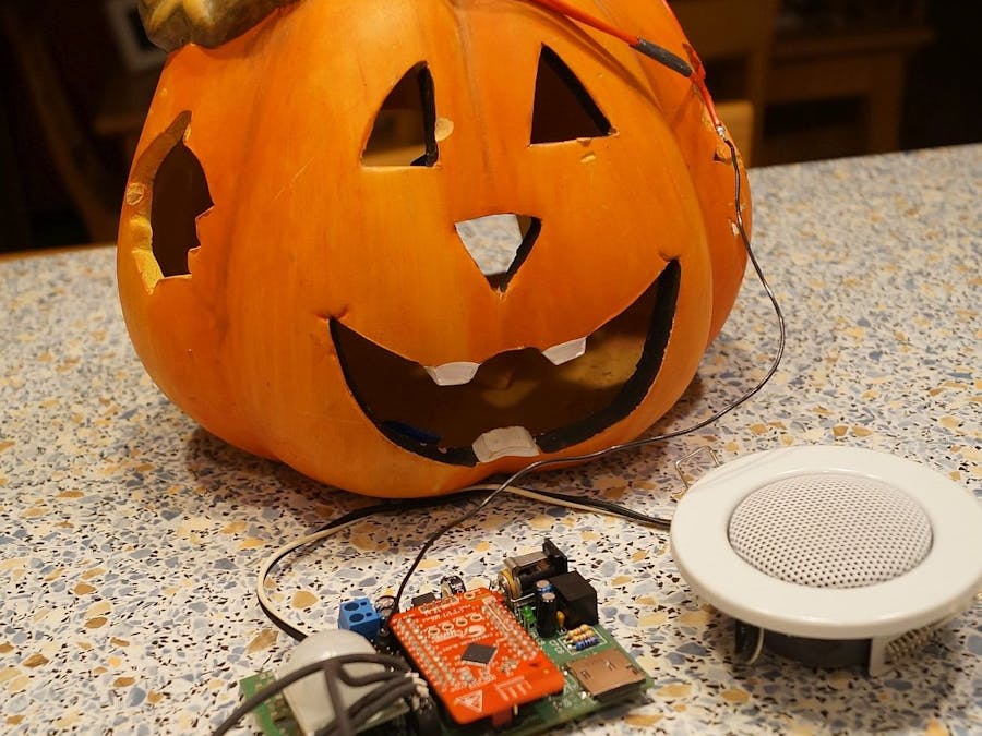
After programming of the CY8CKIT-142 the electronic is ready to run. Related to the initial idea it was mounted into a Halloween Pumpkin.
Last but not least a small Android App has been developed to switch the lights on and to initiate a remote controlled scream. Of course, it's just a simple App that might be enhanced in future to add more features.
After completion the result looks like this:
Well - that's it!
Of course, Halloween is over, but Christmas comes closer ... just change the casing and the sounds ... and realize new objects for different occasions.
Reproduce by yourself and Enjoy!
Regards, Holger


Comments