


Hardware components | ||||||
 |
| × | 1 | |||
 |
| × | 1 | |||
 |
| × | 1 | |||
Software apps and online services | ||||||
 |
| |||||
 |
| |||||
In this project, I connected a voltage sensor module to a NodeMCU ESP8266 and used KiwisIoT to monitor voltage readings online.
The ESP8266 reads the voltage sensor output and sends the measured value through Wi-Fi to the KiwisIoT dashboard.
Basic flow:
Voltage Sensor → ESP8266 → Wi-Fi → KiwisIoT → Dashboard
The main idea is to measure and monitor voltage using a voltage sensor module.
The sensor module scales the input voltage to a level that can be read by the ESP8266 analog input. The ESP8266 reads the analog signal and sends the data to KiwisIoT.
This allows me to view voltage readings remotely through the dashboard without continuously checking the sensor locally.
Note: The voltage range depends on the sensor module being used. The input must be scaled safely to remain within the ESP8266 analog input limits.
Components RequiredHardware
- NodeMCU ESP8266
- Voltage Sensor Module
- Jumper Wires
- USB Cable
- Suitable DC voltage source for testing
Software
- Arduino IDE
- KiwisIoT
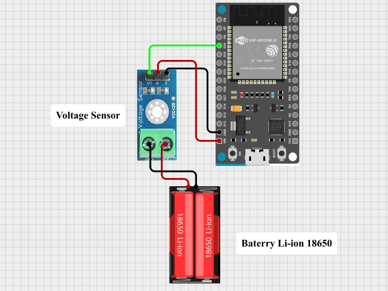
For a typical voltage sensor module with VCC, GND and analog output, the connections are:
Voltage Sensor--->NodeMCU ESP8266
GND ----> GND
OUT / S ----> A0
VCC ----> As required by the sensor module
Some passive voltage divider modules do not require a VCC connection. Check your particular module's pin labels and circuit before wiring it.
Important: Never connect a voltage higher than the permitted A0 input range directly to the ESP8266. The allowable range depends on the particular board's onboard voltage divider. Verify the board specifications before testing.
Arduino ProgramI used the KiwisIoT library to read the voltage sensor and send the value to the dashboard.
The following example assumes a common passive voltage divider module connected to A0. The conversion factor must be calibrated for your specific sensor and board.
#include <KiwisIoT.h>

const char* ssid  = "YOUR_WIFI_NAME";
const char* pass  = "YOUR_WIFI_PASSWORD";
const char* topic = "YOUR_TOPIC_ID";

KiwisIoT kiwisiot(ssid, pass, topic);

#define VOLTAGE_PIN A0

// Example values only.
// Calibrate these for your board and voltage divider.
const float ADC_REFERENCE = 3.3;
const float ADC_MAX = 1023.0;
const float DIVIDER_RATIO = 5.0;

void setup() {
  Serial.begin(9600);
  kiwisiot.begin();
}

void loop() {
  kiwisiot.run();

  int sensorValue = analogRead(VOLTAGE_PIN);

  float measuredVoltage =
      (sensorValue / ADC_MAX) *
      ADC_REFERENCE *
      DIVIDER_RATIO;

  kiwisiot.send("1", measuredVoltage);

  Serial.print("Voltage = ");
  Serial.print(measuredVoltage, 2);
  Serial.println(" V");

  delay(1000);
}
Replace the Wi-Fi details and Topic ID with your own values.
The ADC reference and divider ratio above are example assumptions, not universal values. Calibrate the readings against a suitable multimeter before relying on the measurements. Confirm that the KiwisIoT library accepts floating-point values for send(); if it expects another data type, adapt the value accordingly.
After connecting the ESP8266 to Wi-Fi, I created a dashboard in KiwisIoT.
For this project:
Channel 1 → Voltage Sensor
I used a suitable widget to display the incoming voltage reading.
The basic dashboard flow is:
Voltage Sensor → A0 → ESP8266 → Wi-Fi → KiwisIoT Channel 1 → Widget
The dashboard allows me to monitor voltage readings remotely and observe changes over time.
Applications
This project can be used for basic IoT experiments such as:
- DC voltage monitoring
- Battery voltage monitoring prototypes
- Low-voltage power supply monitoring
- Solar panel voltage monitoring prototypes
- Electronics laboratory experiments
- Remote voltage observation
- IoT learning projects
- Educational power monitoring systems
This setup is intended for suitable low-voltage DC measurements. Measuring mains AC or other hazardous voltages requires appropriately rated, isolated measurement equipment and qualified design.
TroubleshootingVoltage reading is not changing
- Check the sensor output connection to A0.
- Check the common GND connection where required.
- Confirm that the input voltage is changing.
- Check the voltage divider and sensor module specifications.
- Make sure the input is within the safe ADC range.
Dashboard is not receiving data
- Check the ESP8266 Wi-Fi connection.
- Check the KiwisIoT Topic ID.
- Check Channel 1.
- Confirm that the KiwisIoT library is installed correctly.
- Make sure
kiwisiot.run();is insideloop(). - Check the Serial Monitor for readings and connection errors.
Voltage readings are incorrect
- Verify the ADC reference voltage.
- Check the voltage divider ratio.
- Compare the reading with a multimeter.
- Check the ESP8266 board's A0 input range.
- Confirm that the sensor module is designed for the voltage being measured.
Reading is unstable
- Check loose wires and ground connections.
- Use a stable DC source for testing.
- Follow the sensor module's recommended filtering and wiring practices.
- Average multiple ADC readings if appropriate for your application.
After uploading the code, I opened the Serial Monitor at 9600 baud.
Example readings:
Voltage = 3.20 V
Voltage = 3.45 V
Voltage = 3.70 V
Voltage = 3.95 V
These are illustrative values, not actual measurements from a tested setup.
When the input voltage changes, the ESP8266 reads the sensor output, calculates the estimated voltage and sends the result to:
ESP8266
   ↓
Measured Voltage
   ↓
KiwisIoT Channel 1
   ↓
Dashboard
This allows me to monitor voltage readings remotely through the KiwisIoT dashboard.
Questions & Answers1. What does a voltage sensor measure?
It measures an input voltage within the range supported by the sensor module and the connected measurement circuit.
2. Why did I use A0?
I used A0 because the voltage sensor provides an analog output that can be read by the ESP8266 analog-to-digital converter.
3. What does Channel 1 represent?
Channel 1 = Voltage Sensor
4. Does the analog reading directly represent voltage?
No. analogRead() returns an ADC value. The voltage must be calculated using the ADC reference and the sensor's voltage divider ratio.
5. Can I monitor a battery remotely?
Yes. With a suitable voltage divider or compatible voltage sensor module, the ESP8266 can send battery voltage readings to KiwisIoT. Ensure the battery voltage stays within the circuit's rated input range.
6. Can I add another sensor?
Yes. Additional sensors can be connected to available compatible inputs and assigned to other supported KiwisIoT channels.
7. Can I measure AC mains voltage with this circuit?
No. Do not connect AC mains directly to this basic circuit. Mains measurement requires appropriately rated and isolated equipment, suitable protection, and a design intended for that purpose.
8. Can I monitor voltage remotely?
Yes. Once the ESP8266 is connected to Wi-Fi and successfully sends readings to KiwisIoT, the voltage data can be viewed on the dashboar
Channel 1 → Voltage Sensor
I used a suitable widget to display the incoming voltage reading.
The basic dashboard flow is:
Voltage Sensor → A0 → ESP8266 → Wi-Fi → KiwisIoT Channel 1 → Widget
The dashboard allows me to monitor voltage readings remotely and observe changes over time.
How It WorksThe voltage sensor module scales the input voltage to a suitable range for measurement by the ESP8266.
The ESP8266 reads the analog output using:
int sensorValue = analogRead(VOLTAGE_PIN);The analog reading is converted into an estimated input voltage using the ADC reference and voltage divider ratio.
float measuredVoltage =
    (sensorValue / ADC_MAX) *
    ADC_REFERENCE *
    DIVIDER_RATIO;
The calculated voltage is then sent to KiwisIoT using:
kiwisiot.send("1", measuredVoltage);When the input voltage changes, the measured reading can change accordingly and be displayed on the dashboard.
Working FlowDC Voltage Source
↓
Voltage Sensor Module
↓
Scaled Analog Signal
↓
ESP8266 A0
↓
Voltage Calculation
↓
Wi-Fi
↓
KiwisIoT
↓
Channel 1
↓
DashboardThe ESP8266 acts as the bridge between the physical voltage sensor and the online IoT dashboard.
ApplicationsThis project can be used for basic IoT experiments such as:
- DC voltage monitoring
- Battery voltage monitoring prototypes
- Low-voltage power supply monitoring
- Solar panel voltage monitoring prototypes
- Electronics laboratory experiments
- Remote voltage observation
- IoT learning projects
- Educational power monitoring systems
This setup is intended for suitable low-voltage DC measurements. Measuring mains AC or other hazardous voltages requires appropriately rated, isolated measurement equipment and qualified design.
TroubleshootingVoltage reading is not changing
- Check the sensor output connection to A0.
- Check the common GND connection where required.
- Confirm that the input voltage is changing.
- Check the voltage divider and sensor module specifications.
- Make sure the input is within the safe ADC range.
Dashboard is not receiving data
- Check the ESP8266 Wi-Fi connection.
- Check the KiwisIoT Topic ID.
- Check Channel 1.
- Confirm that the KiwisIoT library is installed correctly.
- Make sure
kiwisiot.run();is insideloop(). - Check the Serial Monitor for readings and connection errors.
Voltage readings are incorrect
- Verify the ADC reference voltage.
- Check the voltage divider ratio.
- Compare the reading with a multimeter.
- Check the ESP8266 board's A0 input range.
- Confirm that the sensor module is designed for the voltage being measured.
Reading is unstable
- Check loose wires and ground connections.
- Use a stable DC source for testing.
- Follow the sensor module's recommended filtering and wiring practices.
- Average multiple ADC readings if appropriate for your application.
After uploading the code, I opened the Serial Monitor at 9600 baud.
Example readings:
Voltage = 3.20 V
Voltage = 3.45 V
Voltage = 3.70 V
Voltage = 3.95 V
These are illustrative values, not actual measurements from a tested setup.
When the input voltage changes, the ESP8266 reads the sensor output, calculates the estimated voltage and sends the result to:
ESP8266
   ↓
Measured Voltage
   ↓
KiwisIoT Channel 1
   ↓
Dashboard
This allows me to monitor voltage readings remotely through the KiwisIoT dashboard.
Questions & Answers1. What does a voltage sensor measure?
It measures an input voltage within the range supported by the sensor module and the connected measurement circuit.
2. Why did I use A0?
I used A0 because the voltage sensor provides an analog output that can be read by the ESP8266 analog-to-digital converter.
3. What does Channel 1 represent?
Channel 1 = Voltage Sensor
4. Does the analog reading directly represent voltage?
No. analogRead() returns an ADC value. The voltage must be calculated using the ADC reference and the sensor's voltage divider ratio.
5. Can I monitor a battery remotely?
Yes. With a suitable voltage divider or compatible voltage sensor module, the ESP8266 can send battery voltage readings to KiwisIoT. Ensure the battery voltage stays within the circuit's rated input range.
6. Can I add another sensor?
Yes. Additional sensors can be connected to available compatible inputs and assigned to other supported KiwisIoT channels.
7. Can I measure AC mains voltage with this circuit?
No. Do not connect AC mains directly to this basic circuit. Mains measurement requires appropriately rated and isolated equipment, suitable protection, and a design intended for that purpose.
8. Can I monitor voltage remotely?
Yes. Once the ESP8266 is connected to Wi-Fi and successfully sends readings to KiwisIoT, the voltage data can be viewed on the dashboard.


Comments