


Hardware components | ||||||
 |
| × | 1 | |||
 |
| × | 1 | |||
 |
| × | 1 | |||
 |
| × | 1 | |||
 |
| × | 1 | |||
Software apps and online services | ||||||
| ||||||
Hand tools and fabrication machines | ||||||
| ||||||
| ||||||
I wanted to build a beginner-friendly IoT project where a simple action on a web page could control a real electronic component. I chose an external LED because the result is immediate and easy to verify. The project uses a NodeMCU ESP8266 as the Wi-Fi controller and KiwisIoT as the web-based communication platform.
How the System WorksThe KiwisIoT dashboard contains a Toggle widget. When the Toggle is ON, Channel 1 sends value 1. When it is OFF, Channel 1 sends value 0. The NodeMCU receives this command and changes D2 accordingly.
Complete project workflow.
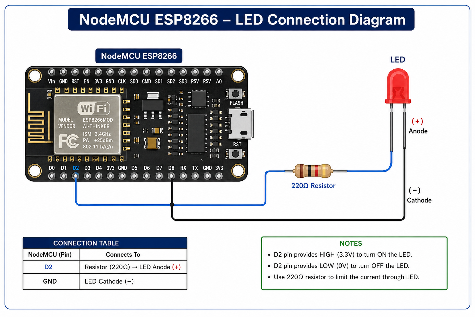
Step 1 — Connect the HardwareConnect the external LED to D2 through a resistor. Connect the other side of the LED to GND.
Wiring: D2 → Resistor → LED anode (+); LED cathode (-) → GND.
My actual NodeMCU and LED hardware setup.
Step 2 — Create the Web DashboardCreate the KiwisIoT dashboard and add a Toggle widget. Configure it to use Channel 1. The ON state sends value 1 and the OFF state sends value 0.
KiwisIoT dashboard with the Toggle control.
Step 3 — Prepare Arduino IDEConnect the NodeMCU ESP8266 using USB.
Open Arduino IDE.
Select the ESP8266 board and correct COM port.
Make sure the KiwisIoT Arduino library is available.
Enter your Wi-Fi SSID, password, and KiwisIoT topic.
Step 4 — Upload the ProgramUsing The programing code to connects the KiwisIoT web dashboard to the physical LED. A Toggle action in the browser changes the LED state through the NodeMCU ESP8266.( The code is in the Attachement File)
Step 5 — Test with Serial MonitorUpload the sketch.
Open Serial Monitor at 9600 baud.
Open the KiwisIoT dashboard.
Switch the Toggle ON and verify Channel 1 / Value 1.
Confirm that the LED turns ON.
Switch the Toggle OFF and verify Channel 1 / Value 0.
Confirm that the LED turns OFF.
Serial Monitor showing the received commands.
Step 6 — Final ResultThe final system successfully connects the KiwisIoT web dashboard to the physical LED. A Toggle action in the browser changes the LED state through the NodeMCU ESP8266.
Final working demonstration.
TroubleshootingLED does not turn ON: check LED polarity, resistor, D2, GND, and the dashboard value.
No command received: check Wi-Fi, topic, Channel 1, and Serial Monitor.
Unexpected result: verify that the Toggle sends 1 for ON and 0 for OFF.
What I LearnedESP8266 Wi-Fi connectivity.
Web-to-hardware IoT communication.
KiwisIoT dashboard control.
Callback-based command handling.
GPIO HIGH/LOW control.
Serial Monitor debugging.
Future ImprovementsControl multiple LEDs using multiple channels.
Add sensors and live dashboard readings.
Add relay control.
Add notifications and event history.
Build a permanent enclosure.


Comments