

Hardware components | ||||||
| × | 1 | ||||
| × | 1 | ||||
| × | 1 | ||||
_iTuZ3KHU3i.png?auto=compress%2Cformat&w=48&h=48&fit=fill&bg=ffffff) |
| × | 1 | |||
 |
| × | 1 | |||
 |
| × | 1 | |||
| × | 1 | ||||
| × | 1 | ||||
Software apps and online services | ||||||
_4YUDWziWQ8.png?auto=compress%2Cformat&w=48&h=48&fit=fill&bg=ffffff) |
| |||||
| ||||||
| ||||||
| ||||||
After getting a WiFi-connected and Alexa-enabled power outlet, I was able to switch on the power of my TV set just with my voice. However switching the TV actually on or switching HDMI inputs still required the old-fashioned remote control.
This needed to change, so the idea of the IRBridge was born.
- Send IR signals to arbitrary devices (e.g. TV, receiver, etc.)
- "Learn" IR commands of existing TV remotes
- Configurable via webinterface, so that changes in IR code, sequence, etc. don't require code changes
- The webinterface should prepared in a way that it would be reusable for future projects
- "Living-room-ready" (i.e. have a nice-looking enclosure)
The project is based on an ESP-12S for the ESP8266's WiFi connectivity, the integrated memory in the ESP-12S board for program code and asset storage and the low price. From a previous project, I already had the required circuit diagram including pull-ups, buttons, etc.
Then a source of power is required. Using a standard micro-USB-socket would allow the device to be powered from something like a USB phone charger, however a voltage regulator is necessary to drop the 5V USB voltage to the 3.3V for the ESP8266. Thankfully Adafruit publishes the diagrams for all their products, so I checked which voltage regulator they were using with their Adafruit Huzzah and decided to also go with the AP2112. Their website is a great resource for anyone working on electronics projects!
For IR connectivity, two components are included in the IRBridge: An IR receiver, to be able to learn IR signals from existing remotes, and four IR leds to transmit the signals. Connecting the IR receiver is straight forward with only 3 connections: power, ground and signal. For the IR leds, I wanted to have more than one and ideally higher-power ones that couldn't be powered directly by the ESP pins. I again got my inspiration from Adafruit and this time their TV-B-Gone Kit together with a lot of googling how to connect transistors. What I didn't consider in the TV-B-Gone Kit, however, is that the voltage of the output pin is the same as the led driver voltage. In the case of the IRBridge, 5V on the led rail must be switched by the ESP pin. Thus I built another NPN transistor into the chain (see schematic).
Two notes on the design:
- I didn't include current limiting resistors for the LEDs. However in case of a bug in the ESP8266 code or another failure, excessive current could flow through the IR leds and fry them.
- Speaking of "another failures", initially I didn't know that the ESP8266 switches some pins to HIGH and some to LOW upon boot and/or code upload. This together with the missing current limiting resistors is a bad thing;-) I had to add another weak pull-down to the NPN base. 10k was too high, 1k did the trick.
The schematic and PCB were designed in KiCad and manufactured by Aisler. Aisler is a relatively new PCB manufacturer based in Germany that also has the option of shipping the required parts with the PCBs. They seem to source the parts from DigiKey. I checked the prices for the IRBridge parts, and it seems that (at least for smaller projects, where one doesn't reach the minimum order amount of DigiKey) sourcing the parts via Aisler is a good deal.
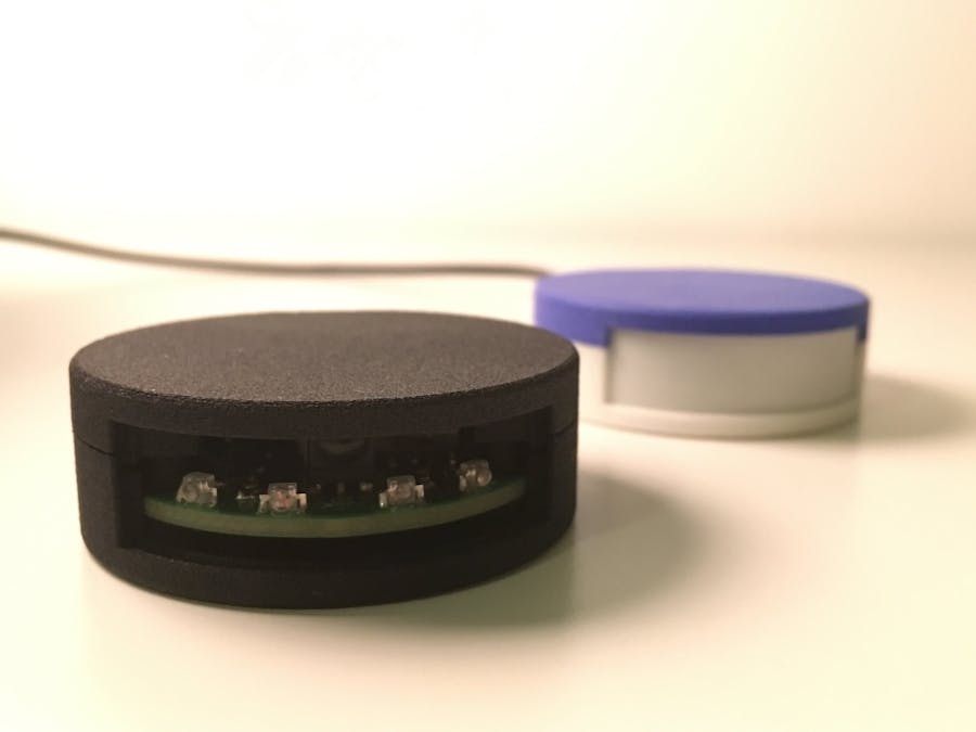
Even though the components are mostly SMD, all is solderable by hand. The soldered end result might not look pretty, but it works:
As written before, a "good looking" enclosure was needed so that the IRBridge can also be used in a living room. I decided to give FreeCAD a try for modelling the enclosure. This is what the final design looks like:
The front of the enclosure can be closed off by either another 3D printed cover or e.g. with IR-transparent film - it just has to be translucent for IR signals.
The PCB has mounting holes built in that fit into posts of the enclosure and make sure that the MicroUSB socket is properly aligned. As I'm always a little sceptical of snap-fit parts (and I like cylindrical head screws;-)), I designed the enclosure to lock with M2 screws and the corresponding M2 nuts.
The encloure was printed via Shapeways, an online 3D printing service with a multitude of available materials. Of course this could also be printed on an FDM printer, but I wanted a print quality and surface finish that comes close to a professional (e.g. injection molded) part. I used their Strong & Flexible Material and at least the black and the white versions are sufficiently IR translucent.
SoftwareI wanted to use this project as a prototype to develop a universal webinterface that could also be easily adapted to future projects. Thus I took the design decision to build the webinterface as a "true" website that would be served from the ESPs SPIFFS memory and not generated on-the-fly, e.g. from PROGMEM.
The actual hardware-related program code is based on the Arduino core for the ESP8266 and makes use of the following libraries:
- ESP Async WebServer as the core library for the webserver
- ArduinoJson for encoding and decoding the JSON format
- IRremoteESP8266 to send and receive IR commands
- FauxmoESP for Alexa connectivity without cloud service (Wemo emulation)
The webinterface is based on Vue.js as the Javascript frontend, Bulma as the CSS framework and axios as well as Buefy as supporting libraries. It has functionality for configuring the IRBridge's Wifi connection, save new IR codes, bundle them in "devices" and expose those devices to Alexa.
This is what the webinterface looks like:
All in all this project was very instructive for myself. I learned a lot about both C++ code development for Arduino/ESP8266 as well as web development with HTML and Javascript on the one hand, and 3D modelling and PCB design on the other hand.
The code could for sure have been done better and is in no way professional, and also the electronics might not be up to the standards of a real product, but I decided anyways to open source the complete project. Let me know via the comment section or on GitHub if any part of the IRBridge helped you with your project - it would be my pleasure;-)


Comments