

Hardware components | ||||||
| × | 1 | ||||
| × | 3 | ||||
| × | 1 | ||||
| × | 1 | ||||
| × | 1 | ||||
| × | 2 | ||||
| × | 2 | ||||
| × | 1 | ||||
| × | 1 | ||||
| × | 1 | ||||
| × | 1 | ||||
| × | 1 | ||||
| × | 1 | ||||
| × | 1 | ||||
| × | 2 | ||||
| × | 1 | ||||
Software apps and online services | ||||||
 |
| |||||
0. Introduction.
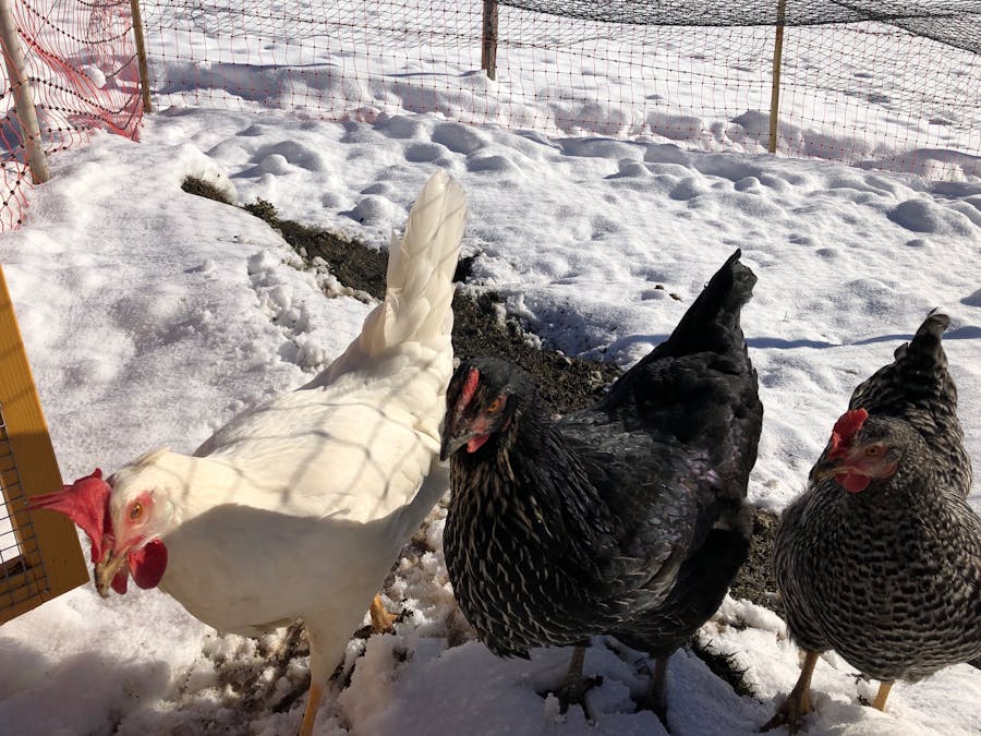
In November 2020 I bought 3 chickens: hobby, conviviality. But, living in the Swiss Alps (low temperatures) and not always at home, I was interested in automating the operation of the light, the door and the heating. Why?
1. Light. It is important that chicken receive sufficient light, specially when daylight is shorter. Not necessarily because you'll have more eggs, important is that they have sufficient time to eat to protect them against the cold. Recommendation is that they receive 13-14 hours of light during a day. And yes, so far I have 3 eggs a day ...!
2. Door. Living remotely, chicken coops are frequently visits by various animals, specially foxes. It is crucial to have the coop securely closed during the night. Having this automated eliminates the risk of forgetting to close/open the door.
3. Heating. In the Swiss Alps, temperatures can occasionally drop to -25 degrees Celsius during the winter. When not at home, it is nearly impossible to guarantee non-frozen water. But even when at home, one needs to refresh the water multiple times during the day.
So, I decided to automate these 3 functions. I opted for an ESP8266 (Wemos D1) solution because of WiFi features, so I can control everything remotely via Cayenne. It was also my wish to be able to monitor the status on my own simple web server.
Not-too-difficult requirements, but it always takes time for everything to function according to your own wishes. Now that everything runs flawlessly, I like to share my experiences on this platform, so that others may be able to use it as well.
1. Overall design.
I have used an ESP8266 device (Wemos D1) with integrated WiFi functionality and sufficient input/output ports for the different sensors and actuators. The schematics for this project are very straightforward, intelligence is the software with algorithms to control light and door using an external real-time clock and to control the heater based on measured temperature. The ESP8266 has a Cayenne (MQTT) interface to display sensor values (i.e., temperature and humidity) and to control light, door and heater using actuators. In addition, relevant information is displayed on an LCD display (20x4) and published on a simple web server.
The ESP8266 is restarted every midnight to reduce the risk of running into issues like resource shortages (e.g., memory).
2. Cayenne dashboard and interface.
There are several ways to use a remote dashboard for displaying sensor values and controlling actuators. I decided not to use Blynk (you need to pay a consumption fee), but Cayenne instead (free, but missing some features like real-time updates of actuator values (i.e., no read back) and sending text messages to be displayed). At the other hand, very easy to configure, visit this link: cayenne.mydevices.com and study the source code. One needs a username/password combination and, for every unique project/dashboard a client identification. In the provided example, a client id is available for both the running implementation and a test environment.
In the source code, it can be easily seen how channels are assigned to sensors and actuators. After the main loop, the Cayenne-related functions are listed. Note that through the Cayenne dashboard, the operating mode can be set to "Manual". In that case, the light/heater/door/reset can be directly controlled, otherwise not.
3. Real-time clock.
In this project, it is crucial to have continuous access to the current date/time. This can be easily solved by connecting to an NTP client. In the source code, it is explained how this functions, very straightforward.
Relevant link: https://www.arduino.cc/reference/en/libraries/ntpclient/.
The most interesting part of this design is probably that the real-time clock data is used for calculating the day number of the year, the day length, the times for sunrise and sunset, as well as the so-called equation of time, all for a specific location (altitude, timezone). These values are used to determine when the light is switched on/off and when the door is to be opened/closed. See the source code for further explanations.
4. Measuring temperature/humidity.
This is a very standard thing for Arduino projects. The device used here is the AM2303 (DHT11), connected to power and ground and outputting value for temperature and humidity. See also this link: https://create.arduino.cc/projecthub/mafzal/temperature-monitoring-with-dht22-arduino-15b013.
5. Controlling light.
The light is controlled through a solid state relay. Using a transistor/diode/resistor combination, when the corresponding ESP8266 output is set to high (D10, > 3VDC), the relay will be switched on, so will the light (up to 380VAC with standard 50 Hz frequency).
A relevant link here is: https://www.homemade-circuits.com/how-to-make-relay-driver-stage-in
6. Controlling door.
Here, a KERBL device is used (https://swifthitch.com/products/kerbl-automatic-door-opener-for-the-chicken-door). It provides internal controls to open and close the door, setting either value to "HIGH" for 1 second.
7. Controlling heater.
The heather is also controlled through a solid state relay. Using a transistor/diode/resistor combination, when the corresponding ESP8266 output is set to high (D11, > 3VDC), the relay will be switched on, so will the light (up to 32VDC).
Here, a VOSS device is used (https://www.electric-fence.co.uk/voss-eisfrei-drinker-heater-for-poultry-drinkers-20-cm-power-adapter-incl-24v-12w.html). It provides internal controls to open and close the door, setting either value from "LOW" to "HIGH" for 1 second.
The heater is turned on when the temperature drops below a certain threshold value and is turned off again when the temperature is above this threshold. To avoid frequent on/off switches, a hysteresis of 2 degrees Celsius has been build in.
The same relevant link as for controlling the light is: https://www.homemade-circuits.com/how-to-make-relay-driver-stage-in
8. Web server.
It has been decided to publish the current status of all relevant parameters as well as list of device events on a local web sever. Nothing sophisticated (html omitted, just plain text).
A relevant link here is: https://tttapa.github.io/ESP8266/Chap10%20-%20Simple%20Web%20Server
9. LED display.
The ESP8266 is also connected (SDA/SCL serial bus interface) to an LCD display with 4 rows of 20 characters each. When in the Cayenne dashboard the operating mode is set to "Manual", the display will be periodically updated with the most relevant information.
See also: https://www.makerguides.com/character-i2c-lcd-arduino-tutorial/
Personally, I have been using the implementation for 4 weeks in a row now, all works smoothly, no problems encountered. The only functionality I would like to add is OTA (Over-the Air-Update), prevents me from having to take the box out and making the update connecting to a PC.
I know that the explanation above is high-level without many details. If I would add them, this story section would easily explode. Instead, I recommend to get a basic understanding of the overall requirements and high-level design, study the available schematics and thoroughly study the source code. In case of any questions, please feel free to contact me, no problem!


Comments