

Hardware components | ||||||
 |
| × | 1 | |||
 |
| × | 1 | |||
|
| × | 1 | |||
 |
| × | 1 | |||
 |
| × | 1 | |||
| × | 1 | ||||
 |
| × | 2 | |||
 |
| × | 1 | |||
| × | 10 | ||||
 |
| × | 10 | |||
Software apps and online services | ||||||
_9nsOFQ7ama.png?auto=compress%2Cformat&w=48&h=48&fit=fill&bg=ffffff) |
| |||||
 |
| |||||
| ||||||
| ||||||
Hand tools and fabrication machines | ||||||
| ||||||
 |
| |||||
A light meter is a device used to measure the amount of light. In photography, a light meter is often used to determine the proper exposure for a photograph. Typically a light meter will include either digital or analog electronic circuit, which allows the photographer to determine which shutter speed and f-number should be selected for an optimum exposure, given a certain lighting situation and film speed.
The modern light meter works according to the principle of a cell (cell) C.C.D. or photovoltaic; An integrated circuit receives a certain amount of light (photons) and transforms it into an analog electrical signal. This signal is visible by the displacement of a needle, the lighting of a diode or the fixation of a figure. A photoresist associated with an ohmmeter would play the same role.
Meter calibration establishes the relationship between subject lighting and recommended camera settings. The calibration of photographic light meters is covered by: ISO 2720:1974 and ISO2721:2013. Applications:
Photography
Many modern cameras include sophisticated multi-segment metering systems that measure the luminance of different parts of the scene to determine the optimal exposure. When using a film whose spectral sensitivity is not a good match to that of the light meter, for example orthochromatic black-and-white or infrared film, the meter may require special filters and re-calibration to match the sensitivity of the film.
Astronomy
In ultraviolet astronomy, measurements are used to discern the chemical composition of the interstellar medium, and the temperature and composition of stars. Because the ozone layer blocks many UV frequencies from reaching telescopes on the surface of the Earth, most UV observations are made from space. Aurora at Jupiter's north pole as seen in ultraviolet light by the Hubble Space Telescope.
Architecture
Lighting or illumination is the deliberate use of light to achieve a practical or aesthetic effect. Lighting includes the use of both artificial light sources like lamps and light fixtures, as well as natural illumination by capturing daylight. Daylighting is sometimes used as the main source of light during day time in buildings. This can save energy in place of using artificial lighting, which represents a major component of energy consumption in buildings. Proper lighting can enhance task performance, improve the appearance of an area, or have positive psychological effects on occupants. Indoor lighting is usually accomplished using light fixtures, and is a key part of interior design. Lighting can also be an intrinsic component of landscape projects.
Cataract Surgery
A cataract is an opacification or cloudiness of the eye's crystalline lens due to aging, disease, or trauma that typically prevents light from forming a clear image on the retina. If visual loss is significant, surgical removal of the lens may be warranted, with lost optical power usually replaced with a plastic intraocular lens. Owing to the high prevalence of cataracts, cataract extraction is the most common eye surgery. Rest after surgery is recommended.
Lux
The lux (symbol: lx) is the SI derived unit of illuminance and luminous emittance, measuring luminous flux per unit area. It´s equal to one lumen per square meter. In photometry, this is used as a measure of the intensity, as perceived by the human eye, of light that hits or passes through a surface. It is analogous to the radiometric unit watt per square meter, but with the power at each wave length weighted according to the luminosity function, a standardized model of human visual brightnessperception. In English, "lux" is used as both the singular and pluralform.
One lux is equal to one lumen per square meter:
1 lx = 1 lm/m2 = 1 cd·sr/m2.
A flux of 1000 lumens, concentrated into an area of 1 square meter, lights up that square meter with an illuminance of 1000 lux. However, the same 1000 lumens, spread out over 10 square meters, produces a dimmer illuminance of only 100 lux.
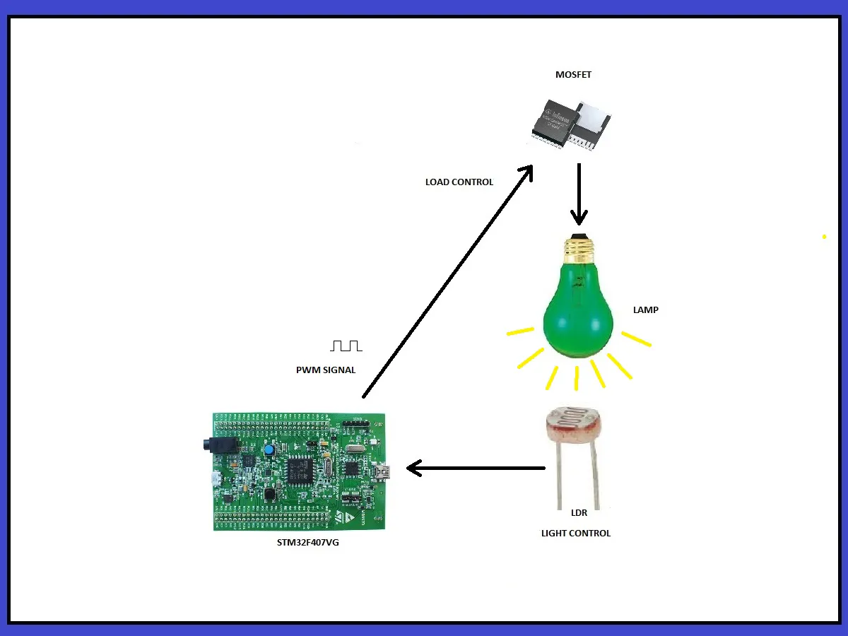
This project has the goal of developing a system with which we can measure and control the amount of lighting that a lamp emits. For our best study, we have divided this project into the following sections:
1. Software Installation
2. Light monitoring and calibration
3. PID Controller
4. Tests
5. Conclusions
(Timing: 6 hrs)
I use the Windows 10 operating system at 32 bits and the software installation is as follows:
a) I have installed "GNAT Programming Studio", and we can download it from the following link: https://www.adacore.com/download/more
In this link I have downloaded and installed the following two programs:
b) We have to install the USB driver of the STM32F407VG board, the link is as follows: https://www.st.com/en/development-tools/stsw-link009.html#getsoftware-scroll. On this site we download the following file: "en.stsw-link009.zip". Once connected the device we verify that it is connected in "Device Manager".
c) To develop this project we work with "Ada Drivers Library", and download it from the following link: https://github.com/AdaCore/Ada_Drivers_Library
In my case, I used the following folder with their examples: https://github.com/AdaCore/Ada_Drivers_Library/tree/master/arch/ARM/STM32/driver_demos
d) To program the "NXP Prototyping Rapid IoT Kit" we have to use the Online IDE. The "Rapid IoT Studio" can be found at the following link:
https://rapid-iot-studio.nxp.com/#%7B%22location%22:%22Studio%22%7D
Here, there´re many examples, and I installed the example demo program: "Rapid IoT Weather Station firmware.bin"
e) PID example By Lowell Cady, is a working example of a PID (Proportional, Integral, Derivative) control and you can download here: https://www.codeproject.com/Articles/36459/PID-process-control-a-Cruise-Control-example
(Timing: 6 hrs)
How does it work?
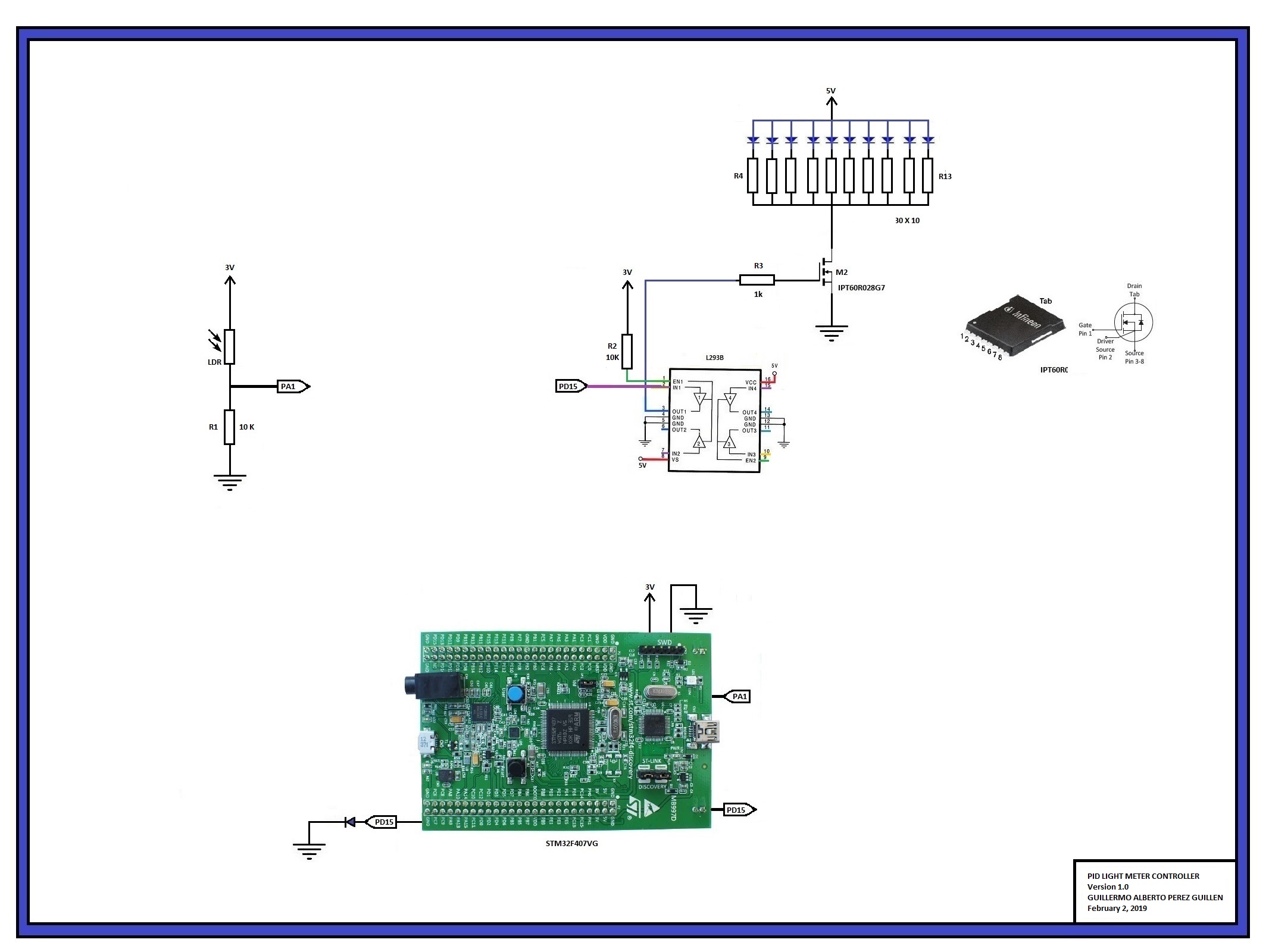
a) A LDR is a special type of resistor. The light-sensitive part of the LDR is a wavy track of cadmium sulphide. As more light falls onto the track, the resistance decreases. It can be used to provide a voltage signal to our STM32F407 which can trigger it into action. This circuit delivers a HIGH voltage when the light is present. A resistor value of 10k is often used.
The variation of the resistance is relatively slow, from 20 to 100 ms depending on the model. This slowness makes it impossible to record rapid variations, such as those produced in artificial light sources powered by alternating current. This behavior can be beneficial, since it gives the sensor a great stability. However, photoresistors are strongly dependent on temperature, so their spectral distribution is affected.
Mathematically, the relationship between the illuminance and the resistance of an LDR follows a potential function.
Ro is the resistance to an Io intensity, both known.
The gamma constant is the slope of the logarithmic graph, or the loss of resistance per decade. It's value typically 0.5 to 0.8.
For this reason, frequently the graphs that relate both values are represented in logarithmic scales for both axes. Under this representation, the relationship is displayed as a linear graph.
The potential behavior makes these small differences involve large variations in the measurement, so it is not possible, in general, to use these values absolutely without a calibration process.
b) The LDR sensor delivers an analog voltage to our port PA1, and this varies from 0 to 3 volts, depending on the light that hits the sensor. The calibration of the light in Ix, I did it by means of a light sensor. The "NXP Rapid IoT" device has a calibrated light sensor, then I turned on a lamp in front of the light sensor and the "Rapid IoT of NXP", later I changed the distance of the lamp and I had the following readings:
c) Sometimes there is too much light creating a "false" signal. For this reason, we have chosen two intermediate signals to do our tests, the values chosen were:
- 43 lx / 1.084 volts / 1480 ADC
- 86 lx / 1.514 volts / 2067 ADC
In relation to the light sensor of the "NXP Rapid IoT Prototyping kit", we have this information:
"A digital ambient light sensor TSL25721FN with programmable interrupt is connected to the K64F MCU through the serial I2C1 interface and one GPIO...
TSL25721FN provides ambient light sensing that approximates human eye response to light intensity. In addition, the operating range is extended to 60, 000 lux in sunlight when the low-gain mode is used."
3. PID Controller(Timing: 1day)
How does it work?
a) If we want to take control of a system, the best solution is to make use of the PID control. There is a lot of information about this and it isn't my goal to expand on this theory that you can find in "Wikipedia" for example. PID is a control loop feedback mechanism widely used in industrial control systems and a variety of other applications requiring continuously modulated control. A PID controller continuously calculates an error value as the difference between a desired setpoint (SP) and a measured process variable (PV) and applies a correction based on proportional, integral, and derivative terms (denoted P, I, and D respectively), hence the name. In my case, STM32F507 board generates a PWM signal of 30 kHz, and the control data are: dt = 0.0005, Kp = 0.025 and Ki =0.025. We used a very small derivative term, and the simulation of my PID system would be the following:
https://en.wikipedia.org/wiki/PID_controller
b) The work of deciding when to apply a PWM control signal is left to the STM32F407 board. In my example, this board does the calculations and generating the PWM control signal.
declare
     Value     : Percentage;
     Raw1      : Long_Float;
--      setpoint  : constant := 1480.0; -- 1.084 volts approx - 43 lx
     setpoint  : constant := 2067.0; -- 1.514 volts approx - 86 lx
     error     : Long_Float := 0.0;
     output    : Long_Float;
     integral  : Long_Float := 0.0;
     dt        : constant := 0.0005;
     Kp        : constant := 0.025;
     Ki        : constant := 0.025;
  begin
     loop
        Start_Conversion (Converter); --adc instruction
        Poll_For_Status (Converter, Regular_Channel_Conversion_Complete, Successful); --adc instruction
        Raw := UInt32 (Conversion_Value (Converter)); -- reading PA1
        Raw1 := Long_Float(Raw * 1);
        error := (setpoint - Raw1);
        integral := (integral + (error*dt));
        output := ((Kp*error) + (Ki*integral));
        Value := Percentage (output); -- duty cycle value
        if Value < 10 then
           Power_Control.Set_Duty_Cycle (10);
        elsif Value > 90 then
           Power_Control.Set_Duty_Cycle (90);
        else
           Power_Control.Set_Duty_Cycle (Value); -- PWM signal
        end if;
c) As we had seen in the previous step, the LDR sensor delivers an analog value to our port PA1, and this is compared to the "setpoint". The "setpoint" is programmed by code, and we did two setpoint tests: 1) 1, 084 volts (1480 ADC); and 2) 1, 513 volts (2067 ADC).
d) For example, if the lighting is low, then the program calculates the error, and generates a PWM signal with a high duty cycle.
e) If the lighting is high, then the program calculates the error, and generates a PWM signal with a small duty cycle.
f) For more details, you can consult the code at the end of this project.
(Timing: 1 day)
Here are some images of the calibration tests done with this system:
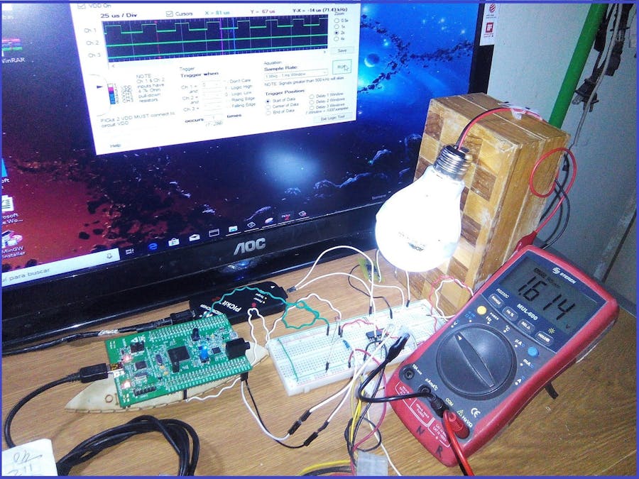
Next, we show some images of the first test with this system (setpoint = 1.084 volts). The PWM signal was captured with the PICkit 2, and the voltage in R1 was measured with a voltmeter.
Below, we show some images of the second test with this system (setpoint = 1.514 volts). The PWM signal was captured with the PICkit 2, and the voltage in R1 was measured with a voltmeter.
Next, we show the video where we demonstrate the operation and results obtained with this system.
5. ConclusionsLight meters or light detectors are also used in illumination. Their purpose is to measure the illumination level in the interior and to switch off or reduce the output level of luminaires. This can greatly reduce the energy burden of the building by significantly increasing the efficiency of its lighting system. It is therefore recommended to use light meters in lighting systems, especially in rooms where one cannot expect users to pay attention to manually switching off the lights. Examples include hallways, stairs, and big halls.
This system proved to be very practical to make use of our "STM32F407" board. Now we understand clearly the concepts of luminescence. It is also clear to us the applications of lighting in professional works to determine more precisely if there is more or less light in a room or concert hall for example. In reality, individual eyes vary slightly in their luminosity functions. However, photometric units are precisely defined and precisely measurable.
Although we had difficulty using the LDR sensor as a light meter, we already have experience and learned the calibration procedure that can be useful in case we use another type of light sensor. The PID control system worked well and surely we will use it in other versions that we will analyze. This is the way forward to improve this system or make a second version in the future.


Comments