

Hardware components | ||||||
 |
| × | 1 | |||
| × | 2 | ||||
 |
| × | 1 | |||
| × | 2 | ||||
| × | 1 | ||||
| × | 1 | ||||
Software apps and online services | ||||||
 |
| |||||
_9nsOFQ7ama.png?auto=compress%2Cformat&w=48&h=48&fit=fill&bg=ffffff) |
| |||||
Hand tools and fabrication machines | ||||||
 |
| |||||
| ||||||
One application of this prototype is in autonomous robots of the future, where they move along long avenues or tunnels and without humans to drive them, so this is a sure way to guide them. It can even be used in parking lots or warehouses where it's necessary to make spaces more efficient.
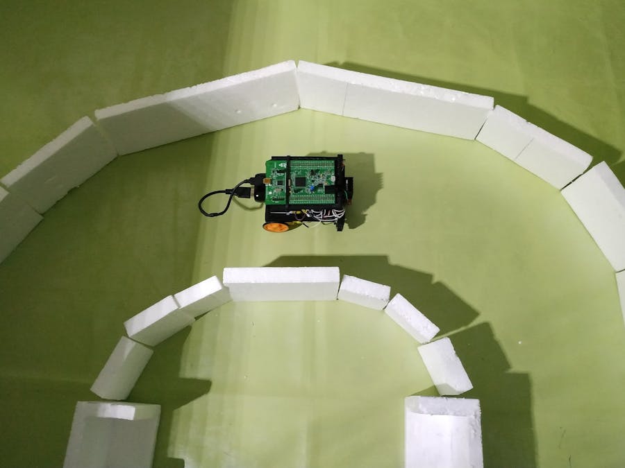
The goal of this project is to design a robot car that moves between two walls by using PID controller on its simplified version. We also want to test the use of infrared distance sensors to achieve our purpose. I have assembled the following road with styrofoam, which has a good response to infrared distance sensors.
Next, you will find all the information in the following order: Hardware, Software, How does the PID Controller work?, Assembling the Chassis, Test and Conclusion.
HARDWARE(Timing: 2 hrs.)
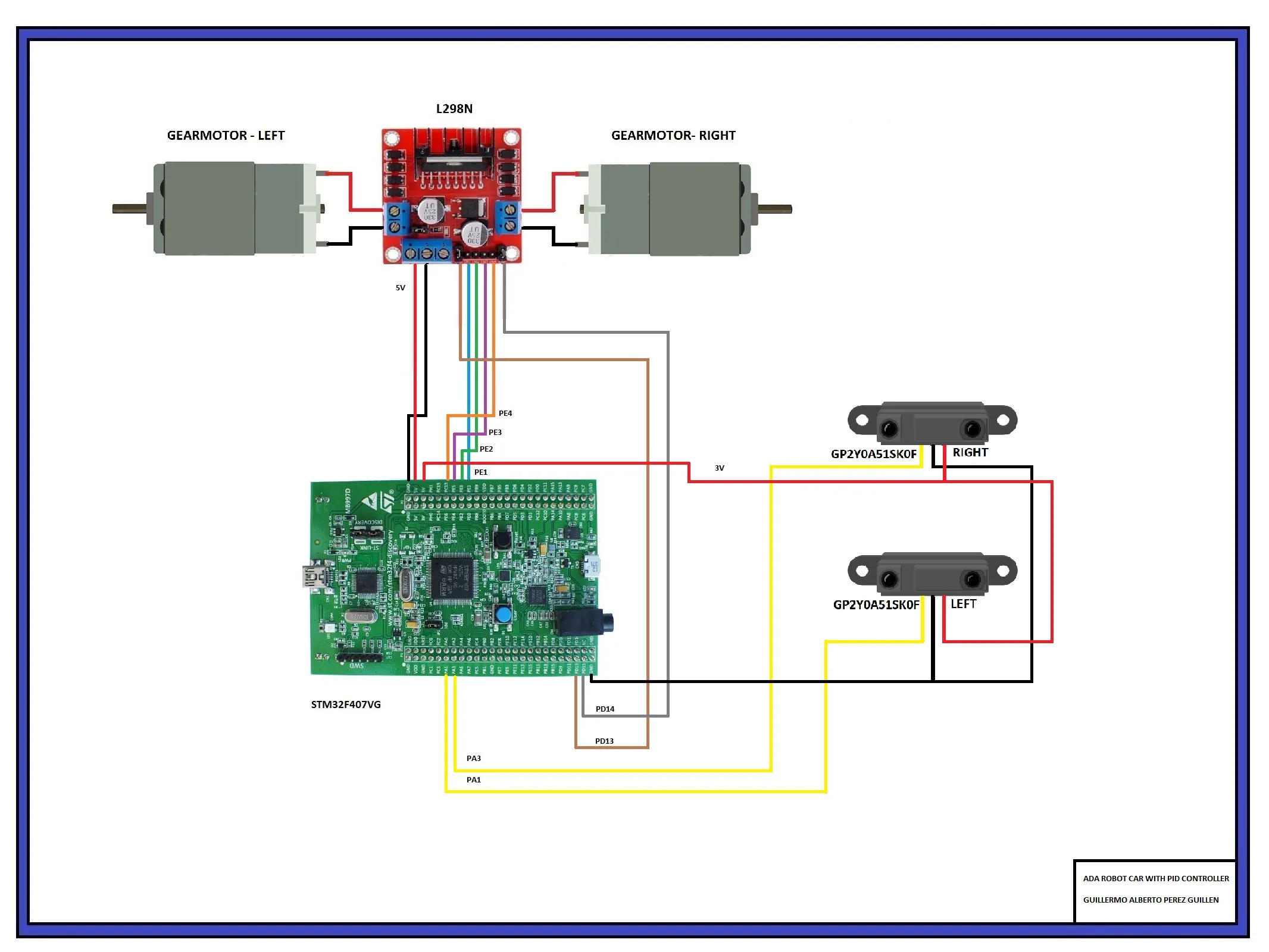
In the figure below I show you the electrical diagram of the robot that I've assembled.
Note: Be careful when connecting the direction of the motors so as not to get an incorrect movement. So make the connections, and then do the tests.
As you can see, the board I used is STM32F407VG, its main features are as follows:
- STM32F407VGT6 microcontroller featuring 32-bit ARM Cortex® -M4 with FPU core, 1-Mbyte Flash memory, 192-Kbyte RAM in an LQFP100 package
- On-board ST-LINK/V2 on STM32F4DISCOVERY or ST-LINK/V2-A on STM32F407G-DISC1
- USB ST-LINK with re-enumeration capability and three different interfaces: Virtual COM port, Mass storage, and Debug port
- Board power supply: – Through USB bus – External power sources: 3 V and 5 V
- LIS302DL or LIS3DSH ST MEMS 3-axis accelerometer
- MP45DT02 ST MEMS audio sensor omni-directional digital microphone
- CS43L22 audio DAC with integrated class D speaker driver
- Eight LEDs: LD1 (red/green) for USB communication, LD2-red for 3.3 V power on, Four user LEDs (LD3-orange, LD4-green, LD5-red and LD6-blue) – 2 USB OTG LEDs LD7-green, VBUS and LD8-red over-current
- Two push buttons (user and reset)
- USB OTG FS with micro-AB connector
For more details, please consult the official website at: https://www.st.com/en/microcontrollers-microprocessors/stm32f407vg.html
GP2Y0A51SK0F (IR Distance Sensor)
Specifications: Maximum range: 15 cm., Minimum range: 2 cm., Sampling rate: 60 Hz., Minimum operating voltage: 4.5 V., Maximum operating voltage: 5.5 V., Supply current: 12 mA., and Output voltage differential: 1.65 V.
Datasheet: https://global.sharp/products/device/lineup/data/pdf/datasheet/gp2y0a51sk_e.pdf
SOFTWARE(Timing: 8 hrs.)
The GPS version that I have used is 19.1 and you can download it at the following link: https://www.adacore.com/download
I'm the author of the following code, and to develop this project, I used the following three examples of Ada Drivers Library: demo_gpio_direct_leds, demo_adc_polling, and demo_timer_pwm. Then I explain in sections, how this code works:
First, we must configure and activate:
- The two analog ports (for monitoring the infrared distance sensors),
- The two pwm channels (to control the speed of the gearmotors), and
- The four GPIO digital ports (to activate the gearmotors).
----------------------------
-- ADC CONFIGURATIONS FOR TWO ADC PORTS    --
----------------------------
Converter     : Analog_To_Digital_Converter renames ADC_1;
Input_Channel : constant Analog_Input_Channel := 5;
Input         : constant GPIO_Point := PA1; -- analog port PA1
Converter3     : Analog_To_Digital_Converter renames ADC_3;
Input_Channel3 : constant Analog_Input_Channel := 3;
Input3        : constant GPIO_Point := PA3; -- analog port PA3
All_Regular_Conversions : constant Regular_Channel_Conversions :=
(1 => (Channel => Input_Channel, Sample_Time => Sample_144_Cycles));
All_Regular_Conversions3 : constant Regular_Channel_Conversions :=
(1 => (Channel => Input_Channel3, Sample_Time => Sample_144_Cycles));
Raw, Raw3 : UInt32 := 0;
Conv1, Conv3, Volts1, Volts3 : Long_Float;
sensor_left, sensor_right : Short_Float;
Successful : Boolean;
Period : constant := 1000;
----------------------------
-- PWM CONFIGURATIONS FOR TWO CHANNELS    --
----------------------------
Output_Channel : constant Timer_Channel := Channel_2; -- ORANGE LED -> PD13 -> Gearmotor left
Output_Channel2 : constant Timer_Channel := Channel_3; -- RED LED -> PD14 -> Gearmotor right
----------------------------
-- GPIO CONFIGURATIONS    --
----------------------------
MOTOR_1A   : GPIO_Point renames PE1; -- L298N DRIVER -> IN1
MOTOR_1B   : GPIO_Point renames PE2; -- L298N DRIVER -> IN2
MOTOR_2A   : GPIO_Point renames PE3; -- L298N DRIVER -> IN3
MOTOR_2B   : GPIO_Point renames PE4; -- L298N DRIVER -> IN4
Pattern : GPIO_Points := (PE1, PE2, PE3, PE4);
procedure Initialize_LEDs;
procedure Configure_Analog_Input;
We create the sine function, and configure the Timer 4 to generate the PWM signal:
----------------------------
-- FUNCTION SINE          --
----------------------------
function Sine (Input : Long_Float) return Long_Float is
Pi : constant Long_Float := 3.14159_26535_89793_23846;
X  : constant Long_Float := Long_Float'Remainder (Input, Pi * 2.0);
B  : constant Long_Float := 4.0 / Pi;
C  : constant Long_Float := (-4.0) / (Pi * Pi);
Y  : constant Long_Float := B * X + C * X * abs (X);
P  : constant Long_Float := 0.225;
begin
return P * (Y * abs (Y) - Y) + Y;
end Sine;
begin
Initialize_LEDs;
----------------------------
-- CONFIGURE TWO PWM CHANNELS --
----------------------------
Enable_Clock (Timer_4);
Reset (Timer_4);
Configure
(Timer_4,
Prescaler     => 1,
Period        => Period,
Clock_Divisor => Div1,
Counter_Mode  => Up);
Configure_Channel_Output
(Timer_4,
Channel  => Output_Channel,
Mode     => PWM1,
State    => Enable,
Pulse    => 0,
Polarity => High);
Configure_Channel_Output
(Timer_4, --
Channel  => Output_Channel2,
Mode     => PWM1,
State    => Enable,
Pulse    => 0,
Polarity => High);
Set_Autoreload_Preload (Timer_4, True);
Enable_Channel (Timer_4, Output_Channel);
Enable_Channel (Timer_4, Output_Channel2);
Enable (Timer_4);
And we configure the resolution and regular conversions of the analog ports:
----------------------------
-- CONFIGURE TWO ANALOG INPUTS --
----------------------------
Configure_Analog_Input;
Configure_Analog_Input3;
Enable_Clock (Converter);
Enable_Clock (Converter3);
Reset_All_ADC_Units;
Configure_Common_Properties
(Mode           => Independent,
Prescalar      => PCLK2_Div_2,
DMA_Mode       => Disabled,
Sampling_Delay => Sampling_Delay_5_Cycles);
Configure_Unit -- CONVERTER UNIT
(Converter,
Resolution => ADC_Resolution_12_Bits,
Alignment  => Right_Aligned);
Configure_Unit  -- CONVERTER 3 UNIT
(Converter3,
Resolution => ADC_Resolution_12_Bits,
Alignment  => Right_Aligned);
Configure_Regular_Conversions -- CONVERTER UNIT
(Converter,
Continuous  => False,
Trigger     => Software_Triggered,
Enable_EOC  => True,
Conversions => All_Regular_Conversions);
Configure_Regular_Conversions -- CONVERTER3 UNIT
(Converter3,
Continuous  => False,
Trigger     => Software_Triggered,
Enable_EOC  => True,
Conversions => All_Regular_Conversions3);
Enable (Converter);
Enable (Converter3);
Monitor and calculate the difference between analog ports PA1 and PA3 to get the error, and through the simplified form of PID controller (error = kp * dif + kd * dif), we can calculate the PWM signals that will be applied to the left and right motors to adjust their speed, and direction of movement of this robot:
----------------------------
-- PID VARIABLES          --
----------------------------
Pulse, Pulse2     : UInt16;
dif : Long_Float := 0.0;
error : Long_Float := 0.0;
integral  : Long_Float := 0.0;
Kp : Long_Float := 0.01;
Kd : Long_Float := 0.01;
begin
loop
Start_Conversion (Converter);
Start_Conversion (Converter3);
Poll_For_Status (Converter, Regular_Channel_Conversion_Complete, Successful);
Poll_For_Status (Converter3, Regular_Channel_Conversion_Complete, Successful);
Raw := UInt32 (Conversion_Value (Converter)); -- LEFT SENSOR
Conv1 := Long_Float(Raw * 1);
Volts1 := (Conv1 * 0.0007326007326007326);
sensor_left := Short_Float(4.5 * (Volts1**(-1))); -- LEFT DISTANCE
Raw3 := UInt32 (Conversion_Value (Converter3)); -- RIGHT SENSOR
Conv3 := Long_Float(Raw3 * 1);
Volts3 := (Conv3 * 0.0007326007326007326);
sensor_right := Short_Float(5.0 * (Volts3**(-1))); -- RIGHT DISTANCE
dif := Conv1 - Conv3;
error := Long_Float((kp*dif)+(kd*(dif))); -- PID CONTROLLER
Pulse := UInt16 (Long_Float (Period / 2) * (1.0 - Sine (error)));
Pulse2 := UInt16 (Long_Float (Period / 2) * (1.0 + Sine (error)));
Set_Compare_Value (Timer_4, Output_Channel, Pulse); -- LEFT GEARMOTOR SPEED
Set_Compare_Value (Timer_4, Output_Channel2, Pulse2); -- RIGHT GEARMOTOR SPEED
-- GO FORWARD --
MOTOR_1A.Set;
MOTOR_1B.Clear;
MOTOR_2A.Set;
MOTOR_2B.Clear;
delay until Clock + Milliseconds (5);
end loop;
As additional information, I have added the calculations of the infrared sensors to measure the distances in centimeters. These information you can get on:
https://www.instructables.com/id/How-to-Use-the-Sharp-IR-Sensor-GP2Y0A41SK0F-Arduin/
HOW DOES THE PID CONTROLLER WORK?(Timing: 2 hrs.)
You can find detailed information about PID controller at: https://en.wikipedia.org/wiki/PID_controller
So you can use Matlab to simulate the behavior of the PID controller. In my case I used "PID Example By Lowell Cady" and in the figure below you can see the graph, which has a stable behavior as time goes by: https://www.codeproject.com/Articles/36459/PID-process-control-a-Cruise-Control-example
In this project, the PID controller does the following:
- The robot is equipped with 2 analog infrared distance sensors, which detect the wall when it is at a distance between 2 and 15 centimeters.
- The sensor reads the information in 12 bits, that is, it gives us a value between 0 and 4095,
- If the sensor is near the wall, the reading will be close to 0 and if it is far away the reading will be high and close to 4095
- The sensor reading is a measure of distance from the robot to the wall
- And the robot can correct its trajectory by changing the speed of its left and right motors by means of a PWM signal.
- As we can see in "image A", if the robot is near to the left wall, then it can decrease the speed of the right motor and increase the speed of the left motor to make the robot move to the right wall, moving away from the left wall
- In "image B", the robot is in the center of the road and it will not make any corrections
- Finally, in "image C", the robot is close to the right wall, so it can decrease the speed of the left motor and increase the speed of the right motor to make the robot move to the left wall, moving away from the right wall
(Timing: 4 hrs.)
The two parts of the chassis that we use in our project I show you in the figures below.
You can get the STL files in the download section. The assembly is very easy, you just have to adjust the gearmotors, the battery, the L298N driver, and the two distance infrared sensors on the main chassis. In the upper chassis, you must place the STM32F407VG board. In the images below I show you some views of the assembly for better understanding.
(Timing: 2 hrs.)
Below I show you the video with the tests performed with this device:
CONCLUSIONThis way of controlling a robot between two walls is very safe, since the robot is immediately placed in the central position of the road and guided by the walls and without impacting them. The hard part is adjusting the kp and kd values of the PID controller, since it takes time. In my case I started with values of 0.1 and I moved them up to 0.01, since I got better results, otherwise the robot oscillates a lot in its movement. I have already done similar things with Arduino and I can tell you that "GNAT Programming Studio" offers me more precision when I work with PID controlller.
It's important to clarify that the movement on the road with curve that your robot can achieve depends on the speed of rotation of the motors (RPM) and the power applied to the motors, so through experimentation you can solve this issue. Now we can start making more complex changes with this robot such as adding a third and fourth sensors and / or combining PID control with neural networks.

Comments