


Hardware components | ||||||
 |
| × | 1 | |||
 |
| × | 1 | |||
 |
| × | 1 | |||
 |
| × | 1 | |||
 |
| × | 1 | |||
| × | 1 | ||||
 |
| × | 1 | |||
 |
| × | 3 | |||
| × | 1 | ||||
Hand tools and fabrication machines | ||||||
 |
| |||||
 |
| |||||
As part of the Lane of Things project, we were interested in creating a node that would be able to collect the varying levels of vibration, C02, temperature and humidity in a classroom.
What did we study and why?
We wanted to study if there is a relationship between the amount of movement caused by people in a room and the air quality of the room. We thought this was an interesting question because we have noticed that places with lots of movement, for example a gym, will have more people breathing and causing dust to move around the place. Adding the sweat released by people exercising may also have an affect on the overall air quality. The truth is that we had no idea to know if these would have an affect on the air quality of a place, which is why it was worth investigating.
Deciding where to deploy
What better place to deploy our node than the dance room! We were guaranteed to have periods of movement during dance classes and periods of rest where no class was active. This made it perfect for our group since this would allow us to compare the different vibration levels caused throughout the day and if they correlated at all to air quality.
Below are pictures of the locations in the dance room where we considered deploying. Things that we considered were proximity to an outlet for power, how easy it would be to collect vibrations, and safety from people stepping on the node.
Prototyping the Sensors
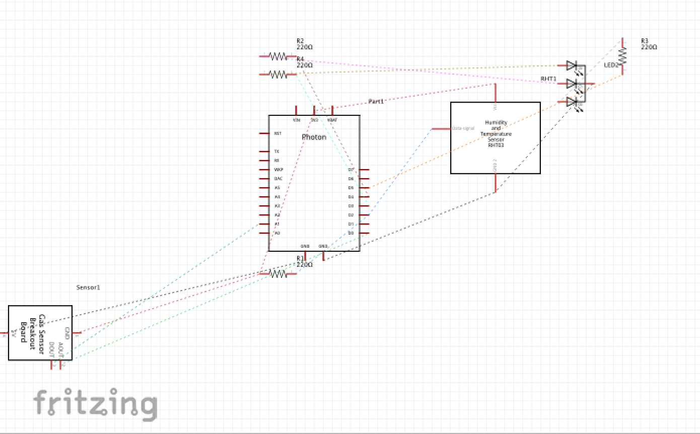
Follow our fritzing diagram to wire your sensors on your breadboard. Make sure you make a particle.io account to be able to write and upload code to the photon. Code can be found in the "attachments" section. Make sure to double check the pins you have assigned your sensors, they may be different from ours so edit the code as you see fit. We used a google sheet to collect our data, but feel free to use anything else that works for you.
Enclosure Design and Construction
We began by measuring the size of each one of the components of our node. For this, we measured our prototype to approximate the dimensions we will need to to house all of the sensors in the enclosure.
Since none of us had prior experience using illustrator and laser cutters, we designed our enclosure the easy way, with makercase.com . All you have to do is input the length, width, and height, plus, you can even engrave onto your enclosure. We decided to engrave our names and our group #, feel free to be creative about yours.
We used T-slot for connecting our enclosure since the screws would make it very easy to disassemble if needed. If you are more experienced feel free to use other methods and other materials. We used wood because it is cheap and we didn't need anything special.
Putting it all together
After the enclosure and breadboard prototype are finished and work properly, feel free to start soldering your photon and sensors onto the pcb.
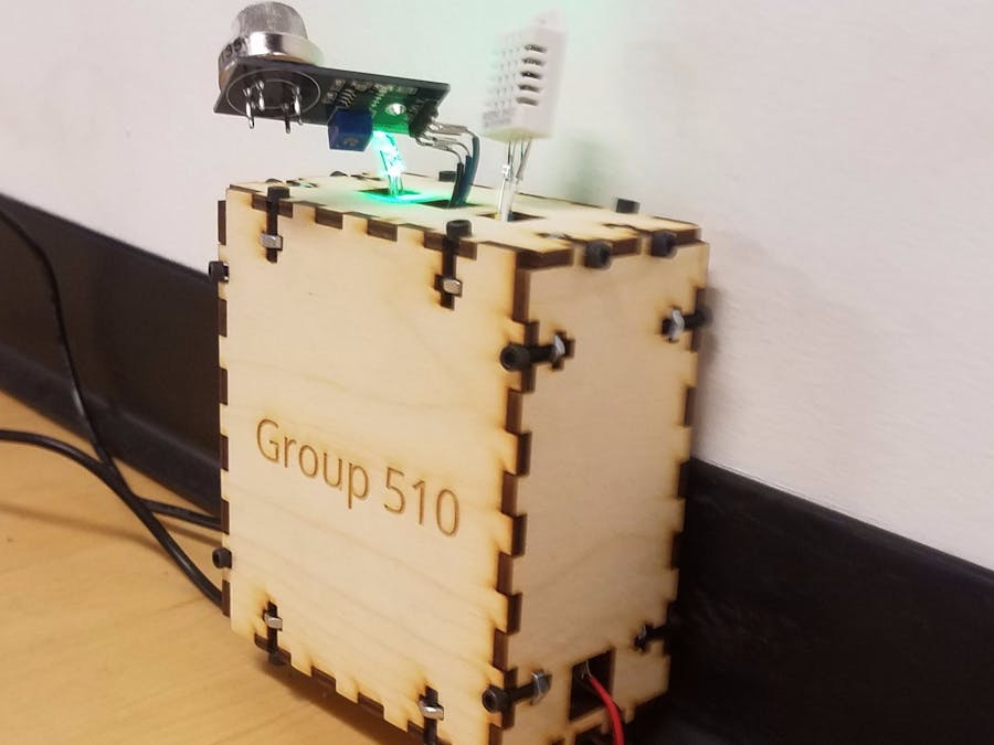
For our enclosure, we decided to make 3 holes on top to leave room for the sensors to be outside of the enclosure. If you will be following a similar design, make sure to leave enough wire for the sensors to reach the openings.
The led you see will light up green if air quality is fine and red if it isn't. Here are pictures of our final node.
Deployment
For deployment, we chose to deploy in the second floor of the dance floor. The vibrations of people dancing could still be felt up there and it was out of people's way so there was no risk of it being stepped on by a dancer. Plus, it was close to a power outlet.
Data
Overall data is listed below
Challenges and Conclusion
While writing the code, everything was working except for the vibration sensor. It simply kept outputting the number 12 onto our Google Sheet. We each looked at the code and were unable to see any errors. Fortunately, when we spoke with a teacher, they were able to point out that we were printing the wrong variable to the Google Sheet. This was a lesson learned for all of us. Small mistakes can make the biggest problems when working too quickly. Take your time and triple check everything, and then check once more.
Thanks,
Group 510


_3u05Tpwasz.png?auto=compress%2Cformat&w=40&h=40&fit=fillmax&bg=fff&dpr=2)
_(1)_iGjrbGAtl7.svg)
Comments