


Hardware components | ||||||
 |
| × | 1 | |||
| × | 1 | ||||
Software apps and online services | ||||||
 |
| |||||
WHO ARE WE
WHAT IS OUR PROJECT
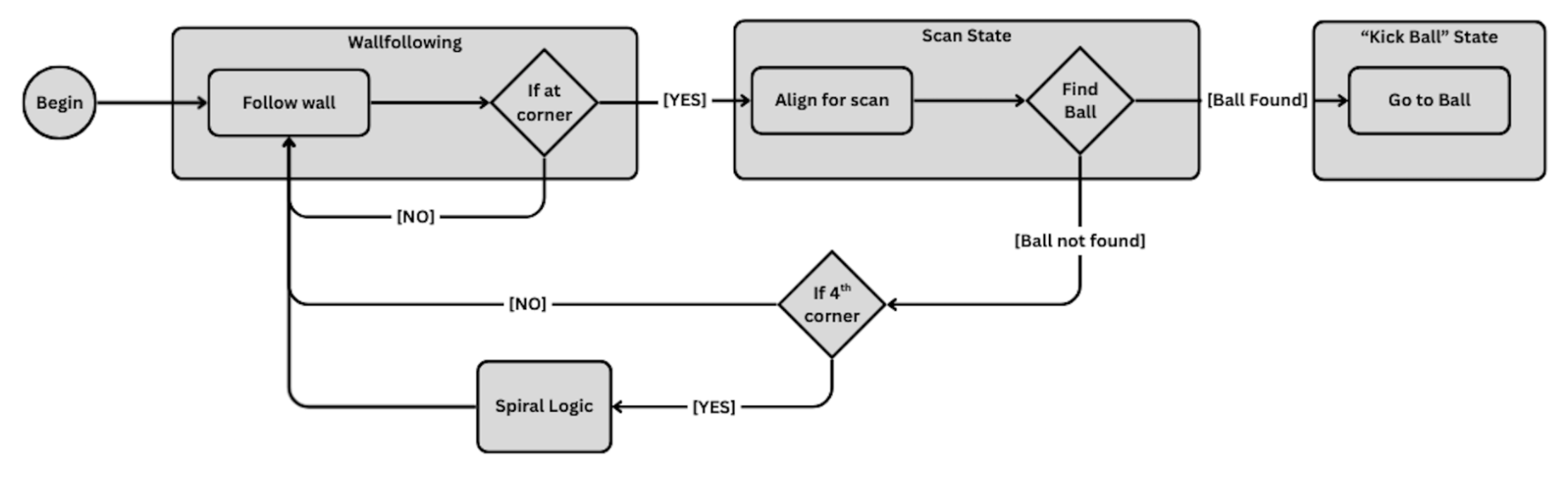
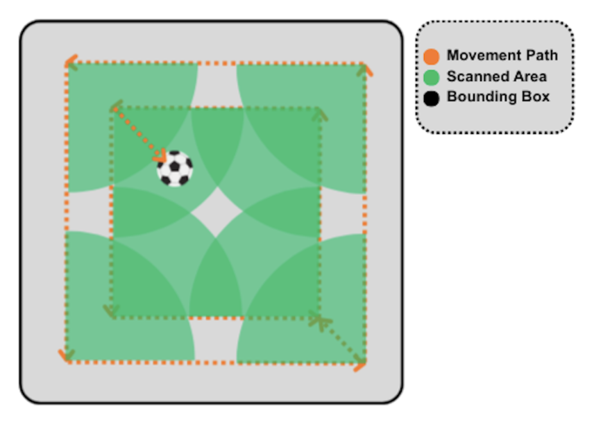
Our Soccerbot runs autonomously inside a large rectangular box, operates without any prior knowledge of the position of the ball, locates it, and kicks it. It will scan for the ball spirally, starting from the edges, using a wall-following algorithm, and does a 90-degree scan every corner. It will move inwards from the wall to the next spiral.
WHY WE DID THIS
We wanted to have a robot running autonomously inside the stadium, which requires very strong logic and data acquisition using the sensors. It is also challenging to incorporate moving the robot in space with the self-balancing Segbot mode, as it requires data prioritization and tuning. We are also very interested in developing an algorithm that the robot has a guaranteed chance of finding the ball and kick it, while preventing any chances of hitting the wall.
HOW IT WORKS
While using the segbot mode, we used the right-wall following algorithm to loop over the walls. When the robot approaches the front-wall in the right-wall following configuration, prior to turning, it will first rotate 180 degrees backwards, and do a 90-degree scan to see if there is a ball near the corner, and also orient itself for the next right-wall following. If there is nothing detected in the scans from the first 4 corners, it will increase its threshold values used for right-wall following to begin scanning in the next spiral.
A Limitation of our project is that the ball is assumed to be placed somewhere in the center, since there are blind spots at places around the midpoints near the walls. If there is no ball detected inside the stadium, the soccerbot will spin around itself at the center of the stadium.
DEMONSTRATION
EXPLANATION


"Soccer Bot" Code
C/C++//#############################################################################
// FILE: LAB6starter_main.c
//
// TITLE: Lab Starter
//#############################################################################
// Included Files
#include <stdio.h>
#include <stdlib.h>
#include <stdarg.h>
#include <string.h>
#include <math.h>
#include <limits.h>
#include "F28x_Project.h"
#include "driverlib.h"
#include "device.h"
#include "F28379dSerial.h"
#include "LEDPatterns.h"
#include "song.h"
#include "dsp.h"
#include "fpu32/fpu_rfft.h"
#include "xy.h"
#define PI 3.1415926535897932384626433832795
#define TWOPI 6.283185307179586476925286766559
#define HALFPI 1.5707963267948966192313216916398
// The Launchpad's CPU Frequency set to 200 you should not change this value
#define LAUNCHPAD_CPU_FREQUENCY 200
// ----- code for CAN start here -----
#include "F28379dCAN.h"
//#define TX_MSG_DATA_LENGTH 4
//#define TX_MSG_OBJ_ID 0 //transmit
#define RX_MSG_DATA_LENGTH 8
#define RX_MSG_OBJ_ID_1 1 //measurement from sensor 1
#define RX_MSG_OBJ_ID_2 2 //measurement from sensor 2
#define RX_MSG_OBJ_ID_3 3 //quality from sensor 1
#define RX_MSG_OBJ_ID_4 4 //quality from sensor 2
// ----- code for CAN end here -----
// Interrupt Service Routines predefinition
__interrupt void cpu_timer0_isr(void);
__interrupt void cpu_timer1_isr(void);
__interrupt void cpu_timer2_isr(void);
__interrupt void SWI_isr(void);
__interrupt void ADCA_ISR (void);
// ----- code for CAN start here -----
__interrupt void can_isr(void);
// ----- code for CAN end here -----
__interrupt void SPIB_isr(void);
void setupSpib(void);
void init_eQEPs(void);
float readEncLeft(void);
float readEncRight(void);
void setEPWM2A(float controleffort);
void setEPWM2B(float controleffort);
void scan(void);
float motor_count = 0;
// Count variables
uint32_t numTimer0calls = 0;
uint32_t numSWIcalls = 0;
extern uint32_t numRXA;
uint16_t UARTPrint = 0;
uint16_t LEDdisplaynum = 0;
int16_t accelx_raw = 0;
int16_t accely_raw = 0;
int16_t accelz_raw = 0;
int16_t gyrox_raw = 0;
int16_t gyroy_raw = 0;
int16_t gyroz_raw = 0;
float uLeft = 5.0;
float uRight = 5.0;
float PosLeft_K = 0.0;
float PosRight_K = 0.0;
float PosLeft_K_1 = 0.0;
float PosRight_K_1 = 0.0;
//float VLeftK = 0.0;
//float VRightK = 0.0;
float e_kL = 0.0;
float i_kl = 0.0;
float u_kL = 0.0;
float v_KL = 0.0;
float i_k_1L = 0.0;
float e_k_1L = 0.0;
float e_kR = 0.0;
float i_kR = 0.0;
float u_kR = 0.0;
float v_KR = 0.0;
float i_k_1R = 0.0;
float e_k_1R = 0.0;
float K_p = 8.88;
float K_i = 15.0;
float V_ref = 0.25;
float Kd = 0.08;
float Ki = 20.0;
float Kp = 3.0;
float intDiff = 0.0;
float intDiff_1 = 0.0;
float errorDiff_1 = 0.0;
float FrontDistance = 0;
float RightDistance = 0;
float xdist = 0;
float ydist = 0;
float Kp_right = -0.03;
float Kp_front = -0.01;
float ref_right = 200;
float ref_front = 1000;
float distfront = 1400;
float distright = 1400;
float threshold1 = 400;
float threshold2 = 300;
float rightwallfollow = 1.0;
int ORDER = 21;
float yk0 = 0.0f;
float yk1 = 0.0f;
float past_states0[22] = { 0.0 };
float past_states1[22] = { 0.0 };
float vel_right = 0.2;
float vel_front = 0.2;
float turn = 0;
float e_turn = 0.0;
float Kp_turn = 3.0;
float accelx = 0;
float accely = 0;
float accelz = 0;
float gyrox = 0;
float gyroy = 0;
float gyroz = 0;
int32_t SpibNumCalls = 0;
float R_old = 0.0;
float L_old = 0.0;
float distR = 0.0f;
float distL = 0.0f;
float printLV3 = 0;
float printLV4 = 0;
float printLV5 = 0;
float printLV6 = 0;
float printLV7 = 0;
float printLV8 = 0;
float x = 0;
float y = 0;
float bearing = 0;
extern uint16_t NewLVData;
extern float fromLVvalues[LVNUM_TOFROM_FLOATS];
extern LVSendFloats_t DataToLabView;
extern char LVsenddata[LVNUM_TOFROM_FLOATS*4+2];
extern uint16_t newLinuxCommands;
extern float LinuxCommands[CMDNUM_FROM_FLOATS];
float b[22]={ -2.3890045153263611e-03,
-3.3150057635348224e-03,
-4.6136191242627002e-03,
-4.1659855521681268e-03,
1.4477422497795286e-03,
1.5489414225159667e-02,
3.9247886844071371e-02,
7.0723964095458614e-02,
1.0453473887246176e-01,
1.3325672639406205e-01,
1.4978314227429904e-01,
1.4978314227429904e-01,
1.3325672639406205e-01,
1.0453473887246176e-01,
7.0723964095458614e-02,
3.9247886844071371e-02,
1.5489414225159667e-02,
1.4477422497795286e-03,
-4.1659855521681268e-03,
-4.6136191242627002e-03,
-3.3150057635348224e-03,
-2.3890045153263611e-03};
float Wr = 0.173;
float thetaL = 0.0;
float xR = 0.0;
float phiR = 0.0;
float x_dot_R = 0.0;
float x_dot_R_1 = 0.0;
float Rwh = 0.0593;
float thetaR = 0.0;
float yR = 0.0;
float theta_dot_avg = 0.0;
float y_dot_R = 0.0;
float y_dot_R_1 = 0.0;
float flag1 = 0.0;
float flag2 = 0.0;
// ----- code for CAN start here -----
// volatile uint32_t txMsgCount = 0;
// extern uint16_t txMsgData[4];
volatile uint32_t rxMsgCount_1 = 0;
volatile uint32_t rxMsgCount_3 = 0;
extern uint16_t rxMsgData[8];
uint32_t dis_raw_1[2];
uint32_t dis_raw_3[2];
uint32_t dis_1 = 0;
uint32_t dis_3 = 0;
uint32_t quality_raw_1[4];
uint32_t quality_raw_3[4];
float quality_1 = 0.0;
float quality_3 = 0.0;
uint32_t lightlevel_raw_1[4];
uint32_t lightlevel_raw_3[4];
float lightlevel_1 = 0.0;
float lightlevel_3 = 0.0;
uint32_t measure_status_1 = 0;
uint32_t measure_status_3 = 0;
volatile uint32_t errorFlag = 0;
// ----- code for CAN end here -----
// ----- code for ADCA global variables start here -----
float adcd0_volts = 0.0f;
float adca0_volts = 0.0f;
float adca1_volts = 0.0f;
int16_t ADCD_ISR_Interrupt_Count = 0;
int16_t ADCA_ISR_Interrupt_Count = 0;
int16_t ADCIND0 = 0;
int16_t ADCIND1 = 0;
int16_t ADCINA2 = 0;
int16_t ADCINA3 = 0;
// ----- global vars for EX2 -----
// Needed global Variables
float accelx_offset = 0;
float accely_offset = 0;
float accelz_offset = 0;
float gyrox_offset = 0;
float gyroy_offset = 0;
float gyroz_offset = 0;
float accelzBalancePoint = -0.71; // OUR COMMENT (EX3): Found this experimentally in EX3, original value -0.76
int16 IMU_data[9];
uint16_t temp=0;
int16_t doneCal = 0;
float tilt_value = 0;
float tilt_array[4] = {0, 0, 0, 0};
float gyro_value = 0;
float gyro_array[4] = {0, 0, 0, 0};
float LeftWheel = 0;
float RightWheel = 0;
float LeftWheelArray[4] = {0,0,0,0};
float RightWheelArray[4] = {0,0,0,0};
// Kalman Filter vars
float T = 0.001; //sample rate, 1ms
float Q = 0.01; // made global to enable changing in runtime
float R = 25000;//50000;
float kalman_tilt = 0;
float kalman_P = 22.365;
int16_t AverageIndex = -1;
float pred_P = 0;
float kalman_K = 0;
int16_t calibration_state = 0;
int32_t calibration_count = 0;
// ----- code for ADCA global variables end here -----
// ---- code for transfer func variables start here -----
float Ak_L = 0.0f;
float Ak_R = 0.0f;
float Vel_Right = 0.0f;
float Vel_Left = 0.0f;
float Ak_L_1 = 0.0f;
float Ak_R_1 = 0.0f;
float Vel_Right_1 = 0.0f;
float Vel_Left_1 = 0.0f;
// ---- code for transfer func variables end here -----
// ----- defining gyro difference equation variables here -----
float gyrorate_dot = 0.0f;
float gyrorate_dot_1 = 0.0f;
float gyro_value_1 = 0.0f;
// ----- defining balancing control variables -----
float ubal = 0.0f;
float K1 = -60.0f;
float K2 = -4.5f;
float K3 = -1.1f;
float K4 = -0.1f;
// --- defining segbot steering variables ---
float WhlDiff = 0.0;
float WhlDiff_1 = 0.0;
float vel_WhlDiff = 0.0;
float vel_WhlDiff_1 = 0.0;;
float turnref = 0.0;
float errorDiff = 0.0;
float turnrate = 0.0;
float turnrate_1 = 0.0;
float turnref_1 = 0.0;
float ForwardBackwardCommand = 0.0;
float eSpeed = 0.0;
float Segbot_refSpeed = 0.0;
float avgWheelVel = 0.0;
float KpSpeed = 0.35;
float KiSpeed = 1.5;
float IK_eSpeed = 0.0;
float IK_eSpeed_1 = 0.0;
float eSpeed_1 = 0.0;
float L = 0.0;
#define NUMWAYPOINTS 8
uint16_t statePos = 0;
pose robotdest[NUMWAYPOINTS]; // array of waypoints for the robot
float corners_x[5] = {0.0, 0.0, 0.0, 0.0, 0.0};
float corners_y[5] = {0.0, 0.0, 0.0, 0.0, 0.0};
int16_t curr_corner_num = 0;
uint16_t flag = 1;
int32_t timer = 0;
//bool start_timer = false;
float ball_x = 0.0;
float ball_y = 0.0;
float ball_phi = 0.0;
bool begin_scan = true;
float initial_angle = 0.0;
bool turn_right = false;
float init_phi = 0.0;
int16_t num_flag = 0;
void main(void)
{
// PLL, WatchDog, enable Peripheral Clocks
// This example function is found in the F2837xD_SysCtrl.c file.
InitSysCtrl();
InitGpio();
// Blue LED on LaunchPad
GPIO_SetupPinMux(31, GPIO_MUX_CPU1, 0);
GPIO_SetupPinOptions(31, GPIO_OUTPUT, GPIO_PUSHPULL);
GpioDataRegs.GPASET.bit.GPIO31 = 1;
// Red LED on LaunchPad
GPIO_SetupPinMux(34, GPIO_MUX_CPU1, 0);
GPIO_SetupPinOptions(34, GPIO_OUTPUT, GPIO_PUSHPULL);
GpioDataRegs.GPBSET.bit.GPIO34 = 1;
// LED1 and PWM Pin
GPIO_SetupPinMux(22, GPIO_MUX_CPU1, 0);
GPIO_SetupPinOptions(22, GPIO_OUTPUT, GPIO_PUSHPULL);
GpioDataRegs.GPACLEAR.bit.GPIO22 = 1;
// LED2
GPIO_SetupPinMux(94, GPIO_MUX_CPU1, 0);
GPIO_SetupPinOptions(94, GPIO_OUTPUT, GPIO_PUSHPULL);
GpioDataRegs.GPCCLEAR.bit.GPIO94 = 1;
// LED3
GPIO_SetupPinMux(95, GPIO_MUX_CPU1, 0);
GPIO_SetupPinOptions(95, GPIO_OUTPUT, GPIO_PUSHPULL);
GpioDataRegs.GPCCLEAR.bit.GPIO95 = 1;
// LED4
GPIO_SetupPinMux(97, GPIO_MUX_CPU1, 0);
GPIO_SetupPinOptions(97, GPIO_OUTPUT, GPIO_PUSHPULL);
GpioDataRegs.GPDCLEAR.bit.GPIO97 = 1;
// LED5
GPIO_SetupPinMux(111, GPIO_MUX_CPU1, 0);
GPIO_SetupPinOptions(111, GPIO_OUTPUT, GPIO_PUSHPULL);
GpioDataRegs.GPDCLEAR.bit.GPIO111 = 1;
// LED6
GPIO_SetupPinMux(130, GPIO_MUX_CPU1, 0);
GPIO_SetupPinOptions(130, GPIO_OUTPUT, GPIO_PUSHPULL);
GpioDataRegs.GPECLEAR.bit.GPIO130 = 1;
// LED7
GPIO_SetupPinMux(131, GPIO_MUX_CPU1, 0);
GPIO_SetupPinOptions(131, GPIO_OUTPUT, GPIO_PUSHPULL);
GpioDataRegs.GPECLEAR.bit.GPIO131 = 1;
// LED8
GPIO_SetupPinMux(25, GPIO_MUX_CPU1, 0);
GPIO_SetupPinOptions(25, GPIO_OUTPUT, GPIO_PUSHPULL);
GpioDataRegs.GPACLEAR.bit.GPIO25 = 1;
// LED9
GPIO_SetupPinMux(26, GPIO_MUX_CPU1, 0);
GPIO_SetupPinOptions(26, GPIO_OUTPUT, GPIO_PUSHPULL);
GpioDataRegs.GPACLEAR.bit.GPIO26 = 1;
// LED10
GPIO_SetupPinMux(27, GPIO_MUX_CPU1, 0);
GPIO_SetupPinOptions(27, GPIO_OUTPUT, GPIO_PUSHPULL);
GpioDataRegs.GPACLEAR.bit.GPIO27 = 1;
// LED11
GPIO_SetupPinMux(60, GPIO_MUX_CPU1, 0);
GPIO_SetupPinOptions(60, GPIO_OUTPUT, GPIO_PUSHPULL);
GpioDataRegs.GPBCLEAR.bit.GPIO60 = 1;
// LED12
GPIO_SetupPinMux(61, GPIO_MUX_CPU1, 0);
GPIO_SetupPinOptions(61, GPIO_OUTPUT, GPIO_PUSHPULL);
GpioDataRegs.GPBCLEAR.bit.GPIO61 = 1;
// LED13
GPIO_SetupPinMux(157, GPIO_MUX_CPU1, 0);
GPIO_SetupPinOptions(157, GPIO_OUTPUT, GPIO_PUSHPULL);
GpioDataRegs.GPECLEAR.bit.GPIO157 = 1;
// LED14
GPIO_SetupPinMux(158, GPIO_MUX_CPU1, 0);
GPIO_SetupPinOptions(158, GPIO_OUTPUT, GPIO_PUSHPULL);
GpioDataRegs.GPECLEAR.bit.GPIO158 = 1;
// LED15
GPIO_SetupPinMux(159, GPIO_MUX_CPU1, 0);
GPIO_SetupPinOptions(159, GPIO_OUTPUT, GPIO_PUSHPULL);
GpioDataRegs.GPECLEAR.bit.GPIO159 = 1;
// LED16
GPIO_SetupPinMux(160, GPIO_MUX_CPU1, 0);
GPIO_SetupPinOptions(160, GPIO_OUTPUT, GPIO_PUSHPULL);
GpioDataRegs.GPFCLEAR.bit.GPIO160 = 1;
//WIZNET Reset
GPIO_SetupPinMux(0, GPIO_MUX_CPU1, 0);
GPIO_SetupPinOptions(0, GPIO_OUTPUT, GPIO_PUSHPULL);
GpioDataRegs.GPASET.bit.GPIO0 = 1;
//ESP8266 Reset
GPIO_SetupPinMux(1, GPIO_MUX_CPU1, 0);
GPIO_SetupPinOptions(1, GPIO_OUTPUT, GPIO_PUSHPULL);
GpioDataRegs.GPASET.bit.GPIO1 = 1;
//SPIRAM CS Chip Select
GPIO_SetupPinMux(19, GPIO_MUX_CPU1, 0);
GPIO_SetupPinOptions(19, GPIO_OUTPUT, GPIO_PUSHPULL);
GpioDataRegs.GPASET.bit.GPIO19 = 1;
//DRV8874 #1 DIR Direction
GPIO_SetupPinMux(29, GPIO_MUX_CPU1, 0);
GPIO_SetupPinOptions(29, GPIO_OUTPUT, GPIO_PUSHPULL);
GpioDataRegs.GPASET.bit.GPIO29 = 1;
//DRV8874 #2 DIR Direction
GPIO_SetupPinMux(32, GPIO_MUX_CPU1, 0);
GPIO_SetupPinOptions(32, GPIO_OUTPUT, GPIO_PUSHPULL);
GpioDataRegs.GPBSET.bit.GPIO32 = 1;
//DAN28027 CS Chip Select
GPIO_SetupPinMux(9, GPIO_MUX_CPU1, 0);
GPIO_SetupPinOptions(9, GPIO_OUTPUT, GPIO_PUSHPULL);
GpioDataRegs.GPASET.bit.GPIO9 = 1;
//MPU9250 CS Chip Select
GPIO_SetupPinMux(66, GPIO_MUX_CPU1, 0);
GPIO_SetupPinOptions(66, GPIO_OUTPUT, GPIO_PUSHPULL);
GpioDataRegs.GPCSET.bit.GPIO66 = 1;
//WIZNET CS Chip Select
GPIO_SetupPinMux(125, GPIO_MUX_CPU1, 0);
GPIO_SetupPinOptions(125, GPIO_OUTPUT, GPIO_PUSHPULL);
GpioDataRegs.GPDSET.bit.GPIO125 = 1;
//PushButton 1
GPIO_SetupPinMux(4, GPIO_MUX_CPU1, 0);
GPIO_SetupPinOptions(4, GPIO_INPUT, GPIO_PULLUP);
//PushButton 2
GPIO_SetupPinMux(5, GPIO_MUX_CPU1, 0);
GPIO_SetupPinOptions(5, GPIO_INPUT, GPIO_PULLUP);
//PushButton 3
GPIO_SetupPinMux(6, GPIO_MUX_CPU1, 0);
GPIO_SetupPinOptions(6, GPIO_INPUT, GPIO_PULLUP);
//PushButton 4
GPIO_SetupPinMux(7, GPIO_MUX_CPU1, 0);
GPIO_SetupPinOptions(7, GPIO_INPUT, GPIO_PULLUP);
//Joy Stick Pushbutton
GPIO_SetupPinMux(8, GPIO_MUX_CPU1, 0);
GPIO_SetupPinOptions(8, GPIO_INPUT, GPIO_PULLUP);
// ----- code for CAN start here -----
//GPIO17 - CANRXB
GPIO_SetupPinMux(17, GPIO_MUX_CPU1, 2);
GPIO_SetupPinOptions(17, GPIO_INPUT, GPIO_ASYNC);
//GPIO12 - CANTXB
GPIO_SetupPinMux(12, GPIO_MUX_CPU1, 2);
GPIO_SetupPinOptions(12, GPIO_OUTPUT, GPIO_PUSHPULL);
// ----- code for CAN end here -----
// ----- code for ADCA start here -----
EALLOW;
//write configurations for all ADCs ADCA, ADCB, ADCC, ADCD
AdcaRegs.ADCCTL2.bit.PRESCALE = 6; //set ADCCLK divider to /4
AdcbRegs.ADCCTL2.bit.PRESCALE = 6; //set ADCCLK divider to /4
AdccRegs.ADCCTL2.bit.PRESCALE = 6; //set ADCCLK divider to /4
AdcdRegs.ADCCTL2.bit.PRESCALE = 6; //set ADCCLK divider to /4
AdcSetMode(ADC_ADCA, ADC_RESOLUTION_12BIT, ADC_SIGNALMODE_SINGLE); //read calibration settings
AdcSetMode(ADC_ADCB, ADC_RESOLUTION_12BIT, ADC_SIGNALMODE_SINGLE); //read calibration settings
AdcSetMode(ADC_ADCC, ADC_RESOLUTION_12BIT, ADC_SIGNALMODE_SINGLE); //read calibration settings
AdcSetMode(ADC_ADCD, ADC_RESOLUTION_12BIT, ADC_SIGNALMODE_SINGLE); //read calibration settings
//Set pulse positions to late
AdcaRegs.ADCCTL1.bit.INTPULSEPOS = 1;
AdcbRegs.ADCCTL1.bit.INTPULSEPOS = 1;
AdccRegs.ADCCTL1.bit.INTPULSEPOS = 1;
AdcdRegs.ADCCTL1.bit.INTPULSEPOS = 1;
//power up the ADCs
AdcaRegs.ADCCTL1.bit.ADCPWDNZ = 1;
AdcbRegs.ADCCTL1.bit.ADCPWDNZ = 1;
AdccRegs.ADCCTL1.bit.ADCPWDNZ = 1;
AdcdRegs.ADCCTL1.bit.ADCPWDNZ = 1;
//delay for 1ms to allow ADC time to power up
DELAY_US(1000);
//Select the channels to convert and end of conversion flag
//Many statements commented out, To be used when using ADCA or ADCB ME 461 4
//ADCA
AdcaRegs.ADCSOC0CTL.bit.CHSEL = 2; //SOC0 will convert Channel you choose Does not have to be A0
AdcaRegs.ADCSOC0CTL.bit.ACQPS = 99; //sample window is acqps + 1 SYSCLK cycles = 500ns
AdcaRegs.ADCSOC0CTL.bit.TRIGSEL = 13;// EPWM5 ADCSOCA or another trigger you choose will trigger SOC0
AdcaRegs.ADCSOC1CTL.bit.CHSEL = 3; //SOC1 will convert Channel you choose Does not have to be A1
AdcaRegs.ADCSOC1CTL.bit.ACQPS = 99; //sample window is acqps + 1 SYSCLK cycles = 500ns
AdcaRegs.ADCSOC1CTL.bit.TRIGSEL = 13;// EPWM5 ADCSOCA or another trigger you choose will trigger SOC1
AdcaRegs.ADCINTSEL1N2.bit.INT1SEL = 1; //set to last SOC that is converted and it will set INT1 flag ADCA1
AdcaRegs.ADCINTSEL1N2.bit.INT1E = 1; //enable INT1 flag
AdcaRegs.ADCINTFLGCLR.bit.ADCINT1 = 1; //make sure INT1 flag is cleared
//ADCB
AdcbRegs.ADCSOC0CTL.bit.CHSEL = 4; //SOC0 will convert Channel you choose Does not have to be B0
AdcbRegs.ADCSOC0CTL.bit.ACQPS = 99; //sample window is acqps + 1 SYSCLK cycles = 500ns
AdcbRegs.ADCSOC0CTL.bit.TRIGSEL = 13; // EPWM5 ADCSOCA or another trigger you choose will trigger SOC0
//AdcbRegs.ADCSOC1CTL.bit.CHSEL = ???; //SOC1 will convert Channel you choose Does not have to be B1
//AdcbRegs.ADCSOC1CTL.bit.ACQPS = 99; //sample window is acqps + 1 SYSCLK cycles = 500ns
//AdcbRegs.ADCSOC1CTL.bit.TRIGSEL = ???; // EPWM5 ADCSOCA or another trigger you choose will trigger SOC1
//AdcbRegs.ADCSOC2CTL.bit.CHSEL = ???; //SOC2 will convert Channel you choose Does not have to be B2
//AdcbRegs.ADCSOC2CTL.bit.ACQPS = 99; //sample window is acqps + 1 SYSCLK cycles = 500ns
//AdcbRegs.ADCSOC2CTL.bit.TRIGSEL = ???; // EPWM5 ADCSOCA or another trigger you choose will trigger SOC2
//AdcbRegs.ADCSOC3CTL.bit.CHSEL = ???; //SOC3 will convert Channel you choose Does not have to be B3
//AdcbRegs.ADCSOC3CTL.bit.ACQPS = 99; //sample window is acqps + 1 SYSCLK cycles = 500ns
//AdcbRegs.ADCSOC3CTL.bit.TRIGSEL = ???; // EPWM5 ADCSOCA or another trigger you choose will trigger SOC3
AdcbRegs.ADCINTSEL1N2.bit.INT1SEL = 0; //set to last SOC that is converted and it will set INT1 flag ADCB1
AdcbRegs.ADCINTSEL1N2.bit.INT1E = 1; //enable INT1 flag
AdcbRegs.ADCINTFLGCLR.bit.ADCINT1 = 1; //make sure INT1 flag is cleared
//ADCD
// OUR COMMENT (EX1): We only need ADCD for Exercise 1.
// OUR COMMENT (EX1): In ADCD we require SOC0, which is setup below. SOC1 is setup for future project application.
// OUR COMMENT (EX1): We provide CHSEL and TRIGSEL, to tell SOC0 which pin the SOC0 needs to convert and to tell SOC0 when to trigger an event(In our case the source of trigger is EPWM5)
AdcdRegs.ADCSOC0CTL.bit.CHSEL = 0; // set SOC0 to convert pin D0
AdcdRegs.ADCSOC0CTL.bit.ACQPS = 99; //sample window is acqps + 1 SYSCLK cycles = 500ns
AdcdRegs.ADCSOC0CTL.bit.TRIGSEL = 13; // EPWM5 ADCSOCA will trigger SOC0
AdcdRegs.ADCSOC1CTL.bit.CHSEL = 1; //set SOC1 to convert pin D1
AdcdRegs.ADCSOC1CTL.bit.ACQPS = 99; //sample window is acqps + 1 SYSCLK cycles = 500ns
AdcdRegs.ADCSOC1CTL.bit.TRIGSEL = 13; // EPWM5 ADCSOCA will trigger SOC1
//AdcdRegs.ADCSOC2CTL.bit.CHSEL = ???; //set SOC2 to convert pin D2
//AdcdRegs.ADCSOC2CTL.bit.ACQPS = 99; //sample window is acqps + 1 SYSCLK cycles = 500ns
//AdcdRegs.ADCSOC2CTL.bit.TRIGSEL = ???; // EPWM5 ADCSOCA will trigger SOC2
//AdcdRegs.ADCSOC3CTL.bit.CHSEL = ???; //set SOC3 to convert pin D3
//AdcdRegs.ADCSOC3CTL.bit.ACQPS = 99; //sample window is acqps + 1 SYSCLK cycles = 500ns
//AdcdRegs.ADCSOC3CTL.bit.TRIGSEL = ???; // EPWM5 ADCSOCA will trigger SOC3
AdcdRegs.ADCINTSEL1N2.bit.INT1SEL = 1; //set to SOC1, the last converted, and it will set INT1 flag ADCD1
AdcdRegs.ADCINTSEL1N2.bit.INT1E = 1; //enable INT1 flag
AdcdRegs.ADCINTFLGCLR.bit.ADCINT1 = 1; //make sure INT1 flag is cleared
EDIS;
// ----- code for ADCA end here -----
// ----- code for EPWM5 init here -----
EALLOW;
EPwm5Regs.ETSEL.bit.SOCAEN = 0; // Disable SOC on A group
EPwm5Regs.TBCTL.bit.CTRMODE = 3; // freeze counter
EPwm5Regs.ETSEL.bit.SOCASEL = 2; // Select Event when counter equal to PRD
EPwm5Regs.ETPS.bit.SOCAPRD = 1; // Generate pulse on 1st event (pulse is the same as trigger)
EPwm5Regs.TBCTR = 0x0; // Clear counter
EPwm5Regs.TBPHS.bit.TBPHS = 0x0000; // Phase is 0
EPwm5Regs.TBCTL.bit.PHSEN = 0; // Disable phase loading
EPwm5Regs.TBCTL.bit.CLKDIV = 0; // divide by 1 50Mhz Clock
// OUR COMMENT(EX1): 1 / 50 Mhz = 2 * 10e-8 gives us the period -> 1 * 10e-3 / (2 * 10e-8) = 50000
//EPwm5Regs.TBPRD = 50000 (This initialization is for 1 ms)
EPwm5Regs.TBPRD = 50000; // Set Period to 1ms sample. Input clock is 50MHz. Dividing it by 4 will change the period to 0.25 ms
// Notice here that we are not setting CMPA or CMPB because we are not using the PWM signal
EPwm5Regs.ETSEL.bit.SOCAEN = 1; //enable SOCA
EPwm5Regs.TBCTL.bit.CTRMODE = 0; //unfreeze, and enter up count mode
EDIS;
// ----- code for EPWM5 init end here -----
// ----- code for CAN start here -----
// Initialize the CAN controller
InitCANB();
// Set up the CAN bus bit rate to 1000 kbps
setCANBitRate(200000000, 1000000);
// Enables Interrupt line 0, Error & Status Change interrupts in CAN_CTL register.
CanbRegs.CAN_CTL.bit.IE0= 1;
CanbRegs.CAN_CTL.bit.EIE= 1;
// ----- code for CAN end here -----
// Clear all interrupts and initialize PIE vector table:
// Disable CPU interrupts
DINT;
// Initialize the PIE control registers to their default state.
// The default state is all PIE interrupts disabled and flags
// are cleared.
// This function is found in the F2837xD_PieCtrl.c file.
InitPieCtrl();
// Disable CPU interrupts and clear all CPU interrupt flags:
IER = 0x0000;
IFR = 0x0000;
// Initialize the PIE vector table with pointers to the shell Interrupt
// Service Routines (ISR).
// This will populate the entire table, even if the interrupt
// is not used in this example. This is useful for debug purposes.
// The shell ISR routines are found in F2837xD_DefaultIsr.c.
// This function is found in F2837xD_PieVect.c.
InitPieVectTable();
// Interrupts that are used in this example are re-mapped to
// ISR functions found within this project
EALLOW; // This is needed to write to EALLOW protected registers
PieVectTable.TIMER0_INT = &cpu_timer0_isr;
PieVectTable.TIMER1_INT = &cpu_timer1_isr;
PieVectTable.TIMER2_INT = &cpu_timer2_isr;
PieVectTable.SCIA_RX_INT = &RXAINT_recv_ready;
PieVectTable.SCIB_RX_INT = &RXBINT_recv_ready;
PieVectTable.SCIC_RX_INT = &RXCINT_recv_ready;
PieVectTable.SCID_RX_INT = &RXDINT_recv_ready;
PieVectTable.SCIA_TX_INT = &TXAINT_data_sent;
PieVectTable.SCIB_TX_INT = &TXBINT_data_sent;
PieVectTable.SCIC_TX_INT = &TXCINT_data_sent;
PieVectTable.SCID_TX_INT = &TXDINT_data_sent;
PieVectTable.SPIB_RX_INT = &SPIB_isr;
// ----- Hardware interrupt to point to our ISR function setup -----
PieVectTable.ADCA1_INT = &ADCA_ISR;
PieVectTable.EMIF_ERROR_INT = &SWI_isr;
// ----- code for CAN start here -----
PieVectTable.CANB0_INT = &can_isr;
// ----- code for CAN end here -----
EDIS; // This is needed to disable write to EALLOW protected registers
// Initialize the CpuTimers Device Peripheral. This function can be
// found in F2837xD_CpuTimers.c
InitCpuTimers();
// Configure CPU-Timer 0, 1, and 2 to interrupt every given period:
// 200MHz CPU Freq, Period (in uSeconds)
ConfigCpuTimer(&CpuTimer0, LAUNCHPAD_CPU_FREQUENCY, 1000);
ConfigCpuTimer(&CpuTimer1, LAUNCHPAD_CPU_FREQUENCY, 4000);
ConfigCpuTimer(&CpuTimer2, LAUNCHPAD_CPU_FREQUENCY, 40000);
// Enable CpuTimer Interrupt bit TIE
CpuTimer0Regs.TCR.all = 0x4000;
CpuTimer1Regs.TCR.all = 0x4000;
CpuTimer2Regs.TCR.all = 0x4000;
init_serialSCIA(&SerialA,115200);
setupSpib();
init_eQEPs();
robotdest[0].x = 2*0.3048; robotdest[0].y = 1*0.3048;
robotdest[1].x = 4*0.3048; robotdest[1].y = 2*0.3048;
//middle of bottom
robotdest[2].x = 4*0.3048; robotdest[2].y = 4*0.3048;
//outside the course
robotdest[3].x = 3*0.3048; robotdest[3].y = 6*0.3048;
//back to middle
robotdest[4].x = 1*0.3048; robotdest[4].y = 7*0.3048;
robotdest[5].x = -1*0.3048; robotdest[5].y = 5*0.3048;
robotdest[6].x = -2*0.3048; robotdest[6].y = 3*0.3048;
robotdest[7].x = 0*0.3048; robotdest[7].y = 0*0.3048;
// Enable CPU int1 which is connected to CPU-Timer 0, CPU int13
// which is connected to CPU-Timer 1, and CPU int 14, which is connected
// to CPU-Timer 2: int 12 is for the SWI.
IER |= M_INT1;
IER |= M_INT6;
IER |= M_INT8; // SCIC SCID
IER |= M_INT9; // SCIA CANB
IER |= M_INT12;
IER |= M_INT13;
IER |= M_INT14;
// Enable TINT0 in the PIE: Group 1 interrupt 7
PieCtrlRegs.PIEIER1.bit.INTx7 = 1;
// Enable SWI in the PIE: Group 12 interrupt 9
PieCtrlRegs.PIEIER12.bit.INTx9 = 1;
PieCtrlRegs.PIEIER6.bit.INTx3 = 1; //SPiB
PieCtrlRegs.PIEIER1.bit.INTx1 = 1;
// ----- code for CAN start here -----
// Enable CANB in the PIE: Group 9 interrupt 7
PieCtrlRegs.PIEIER9.bit.INTx7 = 1;
// ----- code for CAN end here -----
// OUR COMMENT: Setting up EPWM2A
EPwm2Regs.TBCTL.bit.CTRMODE = 0;
EPwm2Regs.TBCTL.bit.FREE_SOFT = 2;
EPwm2Regs.TBCTL.bit.CLKDIV = 0;
EPwm2Regs.TBCTL.bit.PHSEN = 0;
EPwm2Regs.TBCTR = 0;
EPwm2Regs.TBPRD = 2500;
EPwm2Regs.CMPA.bit.CMPA = 1250;
EPwm2Regs.AQCTLA.bit.CAU = 1;
EPwm2Regs.AQCTLA.bit.ZRO = 2;
EPwm2Regs.TBPHS.bit.TBPHS = 0;
// OUR COMMENT: Setting up EPWM2B
EPwm2Regs.CMPB.bit.CMPB = 1250;
EPwm2Regs.AQCTLB.bit.CBU = 1;
EPwm2Regs.AQCTLB.bit.ZRO = 2;
GPIO_SetupPinMux(2, GPIO_MUX_CPU1, 1);
GPIO_SetupPinMux(3, GPIO_MUX_CPU1, 1);
// ----- code for CAN start here -----
// Enable the CAN interrupt signal
CanbRegs.CAN_GLB_INT_EN.bit.GLBINT0_EN = 1;
// ----- code for CAN end here -----
init_serialSCIC(&SerialC,115200);
init_serialSCID(&SerialD,115200);
// Enable global Interrupts and higher priority real-time debug events
EINT; // Enable Global interrupt INTM
ERTM; // Enable Global realtime interrupt DBGM
// ----- code for CAN start here -----
// // Transmit Message
// // Initialize the transmit message object used for sending CAN messages.
// // Message Object Parameters:
// // Message Object ID Number: 0
// // Message Identifier: 0x1
// // Message Frame: Standard
// // Message Type: Transmit
// // Message ID Mask: 0x0
// // Message Object Flags: Transmit Interrupt
// // Message Data Length: 4 Bytes
// //
// CANsetupMessageObject(CANB_BASE, TX_MSG_OBJ_ID, 0x1, CAN_MSG_FRAME_STD,
// CAN_MSG_OBJ_TYPE_TX, 0, CAN_MSG_OBJ_TX_INT_ENABLE,
// TX_MSG_DATA_LENGTH);
// Measured Distance from 1
// Initialize the receive message object 1 used for receiving CAN messages.
// Message Object Parameters:
// Message Object ID Number: 1
// Message Identifier: 0x060b0101
// Message Frame: Standard
// Message Type: Receive
// Message ID Mask: 0x0
// Message Object Flags: Receive Interrupt
// Message Data Length: 8 Bytes (Note that DLC field is a "don't care"
// for a Receive mailbox)
//
CANsetupMessageObject(CANB_BASE, RX_MSG_OBJ_ID_1, 0x060b0101, CAN_MSG_FRAME_EXT,
CAN_MSG_OBJ_TYPE_RX, 0, CAN_MSG_OBJ_RX_INT_ENABLE,
RX_MSG_DATA_LENGTH);
// Measured Distance from 2
// Initialize the receive message object 2 used for receiving CAN messages.
// Message Object Parameters:
// Message Object ID Number: 2
// Message Identifier: 0x060b0102
// Message Frame: Standard
// Message Type: Receive
// Message ID Mask: 0x0
// Message Object Flags: Receive Interrupt
// Message Data Length: 8 Bytes (Note that DLC field is a "don't care"
// for a Receive mailbox)
//
CANsetupMessageObject(CANB_BASE, RX_MSG_OBJ_ID_2, 0x060b0103, CAN_MSG_FRAME_EXT,
CAN_MSG_OBJ_TYPE_RX, 0, CAN_MSG_OBJ_RX_INT_ENABLE,
RX_MSG_DATA_LENGTH);
// Measurement Quality from 1
// Initialize the receive message object 2 used for receiving CAN messages.
// Message Object Parameters:
// Message Object ID Number: 3
// Message Identifier: 0x060b0201
// Message Frame: Standard
// Message Type: Receive
// Message ID Mask: 0x0
// Message Object Flags: Receive Interrupt
// Message Data Length: 8 Bytes (Note that DLC field is a "don't care"
// for a Receive mailbox)
//
CANsetupMessageObject(CANB_BASE, RX_MSG_OBJ_ID_3, 0x060b0201, CAN_MSG_FRAME_EXT,
CAN_MSG_OBJ_TYPE_RX, 0, CAN_MSG_OBJ_RX_INT_ENABLE,
RX_MSG_DATA_LENGTH);
// Measurement Quality from 2
// Initialize the receive message object 2 used for receiving CAN messages.
// Message Object Parameters:
// Message Object ID Number: 4
// Message Identifier: 0x060b0202
// Message Frame: Standard
// Message Type: Receive
// Message ID Mask: 0x0
// Message Object Flags: Receive Interrupt
// Message Data Length: 8 Bytes (Note that DLC field is a "don't care"
// for a Receive mailbox)
//
CANsetupMessageObject(CANB_BASE, RX_MSG_OBJ_ID_4, 0x060b0203, CAN_MSG_FRAME_EXT,
CAN_MSG_OBJ_TYPE_RX, 0, CAN_MSG_OBJ_RX_INT_ENABLE,
RX_MSG_DATA_LENGTH);
//
// Start CAN module operations
//
CanbRegs.CAN_CTL.bit.Init = 0;
CanbRegs.CAN_CTL.bit.CCE = 0;
// // Initialize the transmit message object data buffer to be sent
// txMsgData[0] = 0x12;
// txMsgData[1] = 0x34;
// txMsgData[2] = 0x56;
// txMsgData[3] = 0x78;
// // Loop Forever - A message will be sent once per second.
// for(;;)
// {
//
// CANsendMessage(CANB_BASE, TX_MSG_OBJ_ID, TX_MSG_DATA_LENGTH, txMsgData);
// txMsgCount++;
// DEVICE_DELAY_US(1000000);
// }
// ----- code for CAN end here -----
// IDLE loop. Just sit and loop forever (optional):
while(1)
{
if (UARTPrint == 1 ) {
//serial_printf(&SerialA,"Num Timer2:%ld Num SerialRX: %ld\r\n",CpuTimer2.InterruptCount,numRXA);
// serial_printf(&SerialA,"az: %.3f gx:%.3f, ADCA0: %.3f, ADCA1: %.3f\r\n",accelz,gyroz, adca0_volts, adca1_volts);
//OUR COMMENT(EX1): Verified that the left and right wheel angle readings are accurate and negated the left wheel reading to get positive angles when going forward.
// serial_printf(&SerialA,"Left: %.3f, Right: %.3f\r\n", L_old, R_old);
// serial_printf(&SerialA,"VLeftK: %.3f, VRightK: %.3f\r\n", VLeftK, VRightK);
// serial_printf(&SerialA,"Distance Left: %.3f, Distance Right: %.3f\r\n", distL, distR);
// serial_printf(&SerialA,"D1 %ld D2 %ld",dis_1,dis_3);
// serial_printf(&SerialA," St1 %ld St2 %ld\n\r",measure_status_1,measure_status_3);
serial_printf(&SerialA, "tilt_value: %.3f, gyro_value: %.3f, LeftWheel: %.3f, RightWheel: %.3f\r\n", tilt_value, gyro_value, LeftWheel, RightWheel);
UARTPrint = 0;
}
}
}
// SWI_isr, Using this interrupt as a Software started interrupt
__interrupt void SWI_isr(void) {
// These three lines of code allow SWI_isr, to be interrupted by other interrupt functions
// making it lower priority than all other Hardware interrupts.
PieCtrlRegs.PIEACK.all = PIEACK_GROUP12;
asm(" NOP"); // Wait one cycle
EINT; // Clear INTM to enable interrupts
// Insert SWI ISR Code here.......
if (measure_status_1 == 0) {
RightDistance = dis_1 / sqrt(2);
} else {
RightDistance = 1400;
}
if (measure_status_3 == 0) {
FrontDistance = dis_3;
} else {
FrontDistance = 1400;
}
// ----- code for velocity difference equation start here -----
Ak_L = LeftWheel;
Ak_R = RightWheel;
Vel_Right = 0.6 * Vel_Right_1 + 100 * Ak_R - 100 * Ak_R_1;
Vel_Left = 0.6 * Vel_Left_1 + 100 * Ak_L - 100 * Ak_L_1;
// --- kinematic equations from lab 6 ---
thetaL = LeftWheel;
thetaR = RightWheel;
// OUR COMMENT (EX5): calculating the angle of the robot
phiR = Rwh / Wr * (thetaR - thetaL);
theta_dot_avg = 0.5 * (Vel_Left + Vel_Right);
// OUR COMMENT (EX5): using the angle of the robot, we are able to calcualte the velocity of the robot
x_dot_R = Rwh * theta_dot_avg * cos(phiR);
y_dot_R = Rwh * theta_dot_avg * sin(phiR);
// OUR COMMENT (EX5): by integrating the velocity using the trapezoid rule, we are able to calculate the position of the robot
xR += (x_dot_R + x_dot_R_1) / 2 * 0.004;
// xR = xR_1 + (x_dot_R + x_dot_R_1)*0.004/2
yR += (y_dot_R + y_dot_R_1) / 2 * 0.004;
xdist = xR + (FrontDistance/1000.0)*cos(phiR);
ydist = yR + (FrontDistance/1000.0)*sin(phiR);
// if( xy_control(&Segbot_refSpeed, &turnrate, 0.5, xR, yR, robotdest[statePos].x, robotdest[statePos].y, phiR, 0.25*0.3048, 0.5*0.3048)) {
// statePos = (statePos+1)%NUMWAYPOINTS;
// }
if (numSWIcalls < 2500) {
Segbot_refSpeed = 0;
turnrate = 0;
} else {
if(flag == 1) { // right wall follow state
if (timer > 0) {
timer--;
}
if (rightwallfollow == 1) {
Segbot_refSpeed = 2.0;
turnrate = Kp_right * (ref_right - RightDistance);
if (FrontDistance < threshold1 && RightDistance - ref_right < 50) {
rightwallfollow = 0;
}
} else {
Segbot_refSpeed = 1.0;
turnrate = Kp_front * (ref_front - FrontDistance);
if (timer == 0) {
corners_x[curr_corner_num] = xR;
corners_y[curr_corner_num] = yR;
//start_timer = true;
curr_corner_num += 1;
flag1 = 1.0;
flag = 2; // sweep
// scan here
// if find ball breakout or run some function
// kick ball
// ball_x, ball_y, ball_phi
// flag = false;
}
if (FrontDistance > threshold2) {
rightwallfollow = 1;
}
...
This file has been truncated, please download it to see its full contents.


Comments