1. Why We Started the Project
Driven by the rapid growth of population and economic activities, waste becomes a severe issue worldwide. According to a World Bank report, global annual waste generation is expected to surge by 70% to 3.4 billion tonnes over the next 30 years. The world economy and technology are advancing every day but the problem of waste is deteriorating at an even faster rate. What happens?
In face of this pressing issue, everyone knows "3-R" - Reduce, Reuse, Recycle. We are encouraged to minimise our consumption of goods and waste footprint, to reuse products until the end of the product cycle, and to put into the right bins for recycling. What's next?
More importantly, when looking into the current way of recycling in the society (at least in Hong Kong where GrinBean is founded), it is simply inefficient and, ironically, not helpful to the problem we are faced with. Research from the World Economic Forum suggests that even for the country with the best recycling rate, only below 60% of waste are recycled properly - not to mention some other places such as Hong Kong with only 24%. What to do?
GrinBean is founded to change the status quo. An AI-powered recycling hardware is developed with a vision to boost environmental sustainability. By innovating waste management solutions, educating and taking the community to the next level beyond 3-R, and streamlining waste management to raise recycling rate, GrinBean aims to make recycling accessible everywhere.
We begin with the smallest thing around us - rubbish bin. With the help of image recognition, AI and mechatronics design, GrinBean develops a smart recycling machine, that improves itself while operating, to accurately sort recyclables and filter out inbound contamination.
2. Computer Vision Model Training
Model Training with NVIDIA Jetson Nano
Rather than just inference the model on edge, training on edge is our target, so we tried to train a model with Jetson Nano and at the same time, we train another model on Colab with more computing power.
Step 1: Preporation
Settings on Jetson Nano
With many requirements preinstalled in Jetson Nano, It makes our work much easier. For example, CUDA, openCV and cuDNN are built-in. However, we still do some modifications on the software of Jetson Nano so that it can proceed training and have better detection.
Due to limited amount of RAM in Jetson Nano, an 8G swap file is set on Jetson Nano so it will not run out of memory during training or processing.
The pre-installed opencv-3.3.1 on Jetson Nano does not support gstreamer functionalities. While we are using it for Picamera streaming, we update opencv to 3.4.8 which also gives higher-quality streaming.
Preparing Datasets
Images of recyclable were taken manually one-by-one with the aid of a self-made lightbox to create a uniform shooting environment for producing high-quality data for model training. All the images have a black background color, which matches the environment where detection is carried out inside our recycling machine.
About 4000 recyclables covered including aluminum cans, steel cans, PET bottles, HDPE bottles, cardboard, white paper and color paper. With data augmentation, about a total of 12,000 images are prepared for training.
As we aimed to produce an object recognition model, image annotation is required. The labeling and drawing of the object bounding boxes of images were done using LabelImg, an open-sourced graphical image annotation tool. (More about LabelImg: https://github.com/tzutalin/labelImg)
Step 2: Model Training
We are using darknet framework to train YOLOv3. It is dedicated to real-time object detection. (More info about YOLO model training could be found: https://pjreddie.com/darknet/yolo/, https://github.com/AlexeyAB/darknet, and https://jkjung-avt.github.io/ ) By following the configuration in AlexeyAB/darknet repo, we train a yolov3-tiny model with 3 classes (Paper, Can, Bottle).
On the other hand, we are training another model in Colab with the SAME set of images but different categorisation and configuration. It trains with a full YOLOv3 model with 12 classes.
The training process was also done on AWS EC2 P2 8xlarge Instance. The model training ran through a total of 500 epochs, that took roughly 3 days with aids of NVIDIA GPUs. A PyTorch weight was produced as a result. The outcome was taken as reference for comparison.
Step 3: Testing
Mean Average Precision (mAP) is our key indicator for the model testing. It is associated with IoU which is set to 0.5.
**Although they are trained under different configurations, It shows a reference for the average performance on the same image set.
It is found that the model with 4000 iterations performs the best in mAP.
Screenshot of testing outcomes:
-Testing for YOLOv3-tiny model:
-Testing for full YOLOv3 model:
Step 4: Applying
With the models trained, the best YOLOv3 model trained in Colab, which has tested for 6000 iterations, was used.
The result of the YOLOv3-tiny model is not satisfying that it can’t detect objects accurately. Although the testing statistics show good results, yet in real-world applications, it needs more improvement.
It could be due to the environment and the limitation of the YOLOv3-tiny model. We will keep trying different models and feed in more data for the model.
3. Coordination with NVIDIA Jetson Nano
NVIDIA Jetson Nano is the core processor for our sorting machine that provides a graphical user interface for machine users, detects the recyclables with our trained model and finally processes the items.
Part 1: User Interaction
We have built a desktop application for user interaction that runs on Jetson Nano. When users start recycling, users can put anything into the machine. We will have the detection process running in the backend while the user interface on the machine screen shows the detection result. Users can save their recycling effort record with their phone number or scan QR code with our mobile application and all data will be stored in our database.
Part 2: AI Object Recognition
When the machine is initialised, the AI object recognition programme will be started and running in the background continuously with a camera on. When a recyclable is inserted into the machine, our pre-trained model will classify the object. If the result is any of our predefined classes, the result will be returned to the desktop application. Based on the result, the sorting process is triggered.
Part 3: Hardware Control
When a valid recyclable is detected, the desktop application will send signals to Arduino and it will control all hardware movement in order to sort the recyclable into the designated bin. When this cycle has completed, it is ready to sort the next recyclable.
4. Electronics
Step 1: Set up the Jetson Nano
Instructions can be found here: https://www.waveshare.com/wiki/Jetson_nano_case_(B)
Step 2: Connect all the components according to the schematic below:
Step 3: Test Serial Communication with Arduino
Connect Arduino to Jetson Nano and run the code, check:
1. If the motors are turning at desirable speed and degree when Serial command was sent. If not, check the switches on the side of DM320 which can change the speed and step interval of the motors (details can be found in the documentation of DM320: https://www.omc-stepperonline.com/download/DM320T.pdf, more information about controlling stepper motor with Arduino can be found here: https://forum.arduino.cc/index.php?topic=627348.0);
2. If the ultrasonic are sending back correct data, i.e. move the sensor around and verify the distance.
If everything is working fine, proceed to Part 5.
5. Hardware - Assembling the Machine
The machine mainly consists of (1) the AI and processing module, (2) the mechanical sorting module, (3) sensors, (4) the machine frame and interior structures and (5) optional parts.
AI and processing module
The AI and processing module, consisting of an NVIDIA Jetson Nano connecting to a camera and a touchscreen, is placed next to the machine opening where people put in recyclables. Therefore, when a recyclable is inserted, the camera above can capture its image for image processing and triggering the sorting process. The module is cased in acrylic boards of 5mm thickness for rigidity.
Mechanical Sorting Module
Underneath the AI and processing module is the mechanical sorting module, where the 2 layers of mechanical sorters enable recyclables to be sorted binarily for 2 times, and subsequently sorted into 4 different bins (for plastics, paper, metals, and trash). Please refer to the SolidWorks CAD model and the video:
Sensors
Sensors are installed in various locations, ultrasonic sensors are placed above storage bins to detect their remaining capacities. Information about HC-SR04 (the ultrasonic sensor we use) could be found here: https://howtomechatronics.com/tutorials/arduino/ultrasonic-sensor-hc-sr04/.
Other sensors such as infrared sensors could be installed next to the machine opening for detection of the presence of recyclable.
Sensors are fixed to the frame with tape and Blu Tack.
Machine Structure
The metal frame of the machine is constructed with aluminum extrusions, which serves as the main structure of the machine that allows acrylic boards and other modules to be attached.
When putting 4040 Al extrusions together, be careful with the leveling and make sure they fastened firmly.
It is a bit tricky when installing the motor module. First, fasten the 3D printed part to the motor mount/shaft mount, force is required when necessary because the 3D printed part is not threaded. The most convenient way is to turn the screw directly into the 3D printed part. Otherwise, other options include using a tap drill or use heat insert of the respective thread. More information can be found here: https://markforged.com/blog/heat-set-inserts/.
Then, fasten the 3D printed part along with the Motor Set to the Frame.
Optional Parts
The following are suggested additional parts (not included in the material list) which would not affect functionality if not adopted: a) Machine exterior can be of acrylic or plates of other materials, fixed with bolts and nuts; b) A pair of doors can be added in the front, allowing janitors to collect recyclables from the machine easily; c) A waterproof box to house all electronic components including the power supply and Arduino, for better protection against dirt or moisture.
Final Test
Putting Everything Together
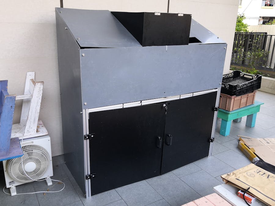
Lastly, the machine should look something like this:


_wzec989qrF.jpg?auto=compress%2Cformat&w=48&h=48&fit=fill&bg=ffffff)


Comments