

Hardware components | ||||||
 |
| × | 1 | |||
| × | 1 | ||||
 |
| × | 1 | |||
Hand tools and fabrication machines | ||||||
 |
| |||||
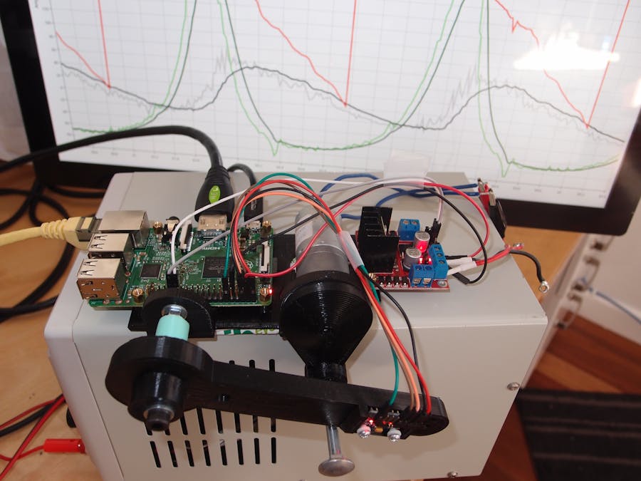
I'm building a wooden mechanical clock that uses gears but also always tells the correct time by knowing where the clock arm positions are. This is a big project, but probably the most interesting is determining the position of the clock arms. This post is about the arm sensing component.
I created a few videos of it in action...
Although my target controller will not be the Raspberry Pi, I'm using it for the prototype because I can use Syncfusion to show graphs.
Just to explain the terms I'm using. The arm moves up and down following the cam on the rotor. The clock arm is not there but has been drawn in yellow and is fixed to the rotor. The sensor will just go up and down rather than round and round with the clock arm. The idea is that you can determine the rotor's angular position based on knowing the angle of the arm.
One of the issues is that there is an ambiguity of where the rotor is compared to the arm. I've plotted it out here... The red line dropping straight down is not a path but rather where the -180 degrees goes to +180 degrees.
Since it is easier to determine the arm angle based on the rotor angle, I calculated these values and created a lookup table to go the other way.
To resolve the ambiguity between the cam of the rotor being close to the pivot point of the arm, I used a Markov chain. This works by saying the probability of the next state is based upon the previous state. Since I know the direction of the motor, I can say probably the next angle is going to be greater than the previous angle.
I'm using a Kalman filter to reduce noise from the accelerometer.
I tried to control the motor using the raspberry PI, but I found it impossible to generate a good PWM signal.
For this reason, I'm going to convert the whole thing over to Arduino.
The hardware schematic is the same as the MPU6050 I did earlier.
I've include a link to the repository for the source code. My 3d print files are pretty bad which why you see a bolt.


Comments