

Hardware components | ||||||
| × | 1 | ||||
 |
| × | 1 | |||
| × | 1 | ||||
| × | 1 | ||||
| × | 1 | ||||
 |
| × | 1 | |||
 |
| × | 1 | |||
| × | 1 | ||||
Software apps and online services | ||||||
 |
| |||||
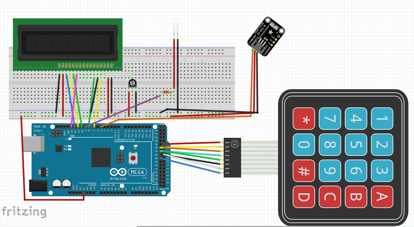
This device is a programmable infrared (IR) universal remote control. In plain English: you point any existing remote control at it, press a button, and it memorizes that button's signal. Then, whenever you press a button on the keypad, it fires that signal back out—just like the original remote would. It can store up to 16 different signals, one for each button on the keypad, and it remembers them even after you turn it off.
Pin LayoutComponent/Arduino Pin
LCD RS/Pin 7
LCD Enable/Pin 8
LCD D4/Pin 13
LCD D5/Pin 10
LCD D6/Pin 11
LCD D7/Pin 12
IR Receiver/Pin 5
IR LED (transmit)/Pin 9
Keypad Rows/Pins 31–34
Keypad Columns/Pins 35–38
How It WorksThe device runs in two modes simultaneously:
Transmit Mode (default): The keypad acts as a remote control. Each button fires whatever IR code has been stored in that slot. If no code has been programmed yet, the LCD tells you.
Learn Mode: Activated by pressing pound (#) twice in quick succession. The LCD displays "Code Ready to Receive." You then point your original remote at the IR receiver and press the button you want to copy. The device captures the code and displays it on the LCD. You then press the keypad button you want to assign it to. Done. The code is saved to EEPROM (permanent memory) and the device returns to transmit mode.
The full learn flow:
- Press # #
- Point remote at receiver, press button
- Press keypad button to assign it to
- LCD confirms "Programmed"
LiquidCrystal(built-in)IRremotev2.6.0 by shirriffKeypadby Mark StanleyEEPROM(built-in)
A few interesting troubleshooting discoveries along the way:
IR LED polarity matters. Unlike thermistors or resistors, IR LEDs only work in one direction. The longer leg (anode) goes toward the signal pin, shorter leg (cathode) to ground.
Heat kills IR LEDs. Scavenging an IR LED from an old remote and desoldering it with too much heat can fry the internal junction even if it looks fine on the outside. Use a fresh LED from a supplier.
The Arduino Mega uses pin 9 for IR transmission. The IRremote library defaults to different pins depending on the board. On the Mega, pin 9 is the hardware PWM pin used for IR output—not pin 2 like on an Uno. This was the key fix that got transmission working.
Metal shorts are sneaky. A battery accidentally touching pins on the back of the Arduino caused an LCD display failure. The fix was reseating all the connections and adjusting the contrast potentiometer.


Comments