

Hardware components | ||||||
 |
| × | 1 | |||
 |
| × | 1 | |||
_ztBMuBhMHo.jpg?auto=compress%2Cformat&w=48&h=48&fit=fill&bg=ffffff) |
| × | 1 | |||
The ATtiny85 is a wonderful little chip that can run Arduino code, even on a coin cell battery, which makes it a perfect starter platform for building your own PCB badges.
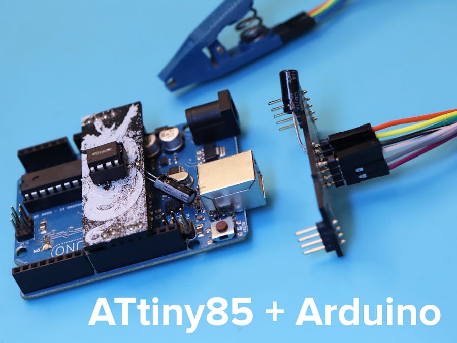
I recently created my own ATtiny85 programmer board, following a tutorial by Arjun Ganesan. Eventually, I wanted to make a really low-profile badge for Avnet's centennial, using only surface-mount components. Here's how to use my board to program BOTH through-hole (DIP) and surface-mount (SOIC) versions.
Video guide:
SetupWhen you order the boards from OSH Park, they come in sets of 3. If you order from a different supplier, buy 2 or more so you can program both types of ATtiny85 IC.
Assemble the boards by soldering the male headers and 10uF capacitor to the bottom (labeled side). Attachments for interfacing with the chip will go on the top (art side). For programming DIP chips, solder on an 8-pin socket. For programming SOICs, add two sets of 4-pin male headers, pointing up. Attach female jumper wires and an SOIC test/programmer clip.
By the way – if you don't like my board's visual design and want to make your own, you can grab the KiCad files from my previous tutorial!
Programming in the Arduino IDEWhen you have your chips attached (as described below), follow Arjun Ganesan's guide for programming. You'll need to set up Arduino to recognize these chips and program them with the "Arduino as ISP" option. Then, burn the bootloader (via the Tools menu) and then upload the code. Burning the bootloader may only take a few seconds, and it enables the chip to receive and store Arduino code. Uploading the code can take a bit longer, but shouldn't be more than a few minutes.
1. Setting up through-hole (DIP) chipsATtiny85 chips in the DIP format have legs/pins pointing downward. They usually come packaged in a cut plastic rail. Often, the legs are bent outward slightly. You can place them sideways on a flat surface and lean them over to straighten out the legs to 90º so they will fit in the socket. (See video for a visualization.)
Place a chip in the socket, paying attention to where the little dot or divot indicates Pin 1. It should go on the bottom left, matching up to where there may be a divot on the left side of the socket. (If there isn't a marking on the socket, you might want to make one!)
Then, follow the Arduino programming instructions above.
2. Programming surface-mount (SOIC) chipsFor surface-mount chips, you'll program them after you already have them soldered down to a board. This is due to how the clip works: it grabs the main body of the chip, from above, and if the chip isn't soldered down, it will rotate and slip around.
So, first, make sure you've properly attached the female-female jumper wires: when you look down at the pins on the programmer, and on the clip, they should both have the same arrangement of attached wires. Think about it this way: the pins will be arranged the same way whether you have the chip plugged into the programmer board, or are grabbing the chip from above with the programming clip.
Squeeze the clip open and settle it down over the pins on the chip. Press it down to your PCB's surface. Then, since I'd hand-soldered my chips and the connections weren't perfectly beautiful, I found it useful to squeeze the jaws of the clip together on the chip to ensure a good connection. (See the video above for a visual demonstration.)
Then, follow the Arduino programming instructions above.


Comments