

EEG is revving up hard among quantified-self groups, makers, and researchers of sleep and learning. Here's how I updated my headset by embedding it in a pair of industrial earmuffs, which are worn around the neck. It looks cyberpunk and almost fashionable – and is much more comfortable for extended wear!
DISCLAIMER: Perform this hack at your own risk! It's possible you could wreck your headset. It definitely voids the warranty. Don't say I didn't warn you.
...So, after you buy a MindFlex and follow the tutorial, you'll be rocking something like this:
...Which is suboptimal. The end product looks like this:
...Let's go! Starting with a pair of industrial sound-protective earmuffs, remove the padding:
This leaves two large spaces to tuck our electronics into.
Next, dig into the headset. Begin by removing the batteries, then cut the wires connecting the battery case to the set.
Remove the casing on the other side, as well; you'll see that the elastic is held in place via a metal bar that clicks into the plastic enclosure. Just slide out the bar, and the headband comes free.
I like to store small parts on a sticker, which I can fold over if I need to keep them secure until the next session:
Now, we'll pull out the circuit board and sensors. The ear clip is already free of the enclosure, since it simply rests in a slot between the two halves of the enclosure.
To free the forehead sensor, cut open the elastic band, being careful not to sever the cables.
Now, you'll learn a bit about the forehead sensor used in the MindFlex. It's actually just a piece of conductive fabric, held pressed to the forehead with a trapezoidal foam block. Oddly, the white cable running to this fabric is intertwined with a black ground cable -- which doesn't connect to anything at all! It's capped off near the sensor with a piece of heat-shrink tubing. Feel free to cut off this cable; doing so has produced no discernible difference in how well my headset works. (Connectivity is the same or better, compared to the original set.)
I replaced the whole conductive-fabric setup with a single black electrode cable, like this one. It doesn't even have the conductive snap-in piece: since the snap fitting itself is conductive, and you don't need a broad sensing area, you can simply attach that to your forehead with a timelessly stylish Band-Aid. :)
At this point, I de-soldered the sensors and power cables from the circuit board so that I could thread them through a hole I Dremeled into the earmuff casing. I slotted the MindFlex board into the earmuff, then reattached those cables and added a bit of hot glue for strain relief. I didn't attach anything to the muff, in case I needed to pull it out again in the future.
Here's where I soldered and heat-shrunk the forehead sensor cable together. It's not staggeringly pretty, but it works. You can see the truncated ground wire as well, wrapped partly around the ear sensor cable.
I Dremeled the battery case out of its plastic enclosure. It was a narrow fit to get it into the muffs, but that's good: I can insert and remove the batteries, but the case stays in.
As with all cylinder battery cases, there are two metal contacts on the outside, to which the power and ground cables are connected. I removed the old, shortish ones, and added a new, longer, dual black cable. It looks better, and it's wound around the earmuffs' adjustable headband, where the spiral can be pulled apart or squished together to accommodate the changing length. This enables you to get a comfortable fit around your neck.
I also installed a switch in the power cable, so that I could still turn the unit on and off. (It still has a separate power source from the Pinoccio.) I Dremeled a rough hole in the top of the casing for that, and poked the switch through – someday soon, I will add hot glue to hold it in place. Another hole allows the power cable to come through.
Of course, the power cable is also soldered onto the circuit board on the other side.
Now that the MindFlex is all connected up, switch it on and make sure the green light illuminates. If not, go back and check your power connections.
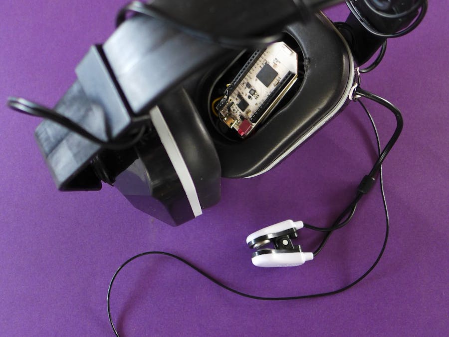
Time to add the Pinoccio! You can simply tuck it in, on top of the EEG circuit board.
As a final note, I originally added an external power switch for the Pinoccio Scout as well. I later removed it, since i added unnecessary extra cabling and it's just as easy to reach in and toggle the Scout's power switch directly. But I did like the little mini-breadboard I whipped up out of a header, so I'll pass along that hack as well:
On the left, I soldered the first eight header pins together, using a clipped-off LED leg (those do come in handy sometimes). That's seven pins connected to a common ground, since lots of things usually get plugged in there. Then, I made four little paired connections, just using globules of solder. (It's easiest if you bend the pins together first.)
You can plug any two small wires into a pair of these pins to link them. Pretty useful when you're prototyping – definitely better than twisting cables together! A generous glob of hot glue proofs the setup against short-circuits.
So, we come to the end of our tutorial! The final result looks like this:
...Classy! (?)


Comments