


Hardware components | ||||||
 |
| × | 1 | |||
 |
| × | 1 | |||
 |
| × | 1 | |||
 |
| × | 1 | |||
 |
| × | 1 | |||
 |
| × | 1 | |||
 |
| × | 1 | |||
 |
| × | 1 | |||
 |
| × | 1 | |||
 |
| × | 1 | |||
Hand tools and fabrication machines | ||||||
 |
| |||||
 |
| |||||
Motivation: Diagnosing Severity of Hand Tremors
When treating patients with hand tremors, it is important for doctors to determine how severe the tremor to diagnose the appropriate treatment.
Currently, a process called the “Tapping Test” is used to screen for the presence of tremors and ataxia, as part of the Scale for Assessment and Rating of Ataxia (SARA). During this procedure, the patient takes a pen and repeatedly taps it as fast as they can, then the doctor listens to the speed and degree of regularity of the rhythm. However, an issue with this test is it very subjective and prone to human error and inconsistencies, depending on the doctor conducting it. It is a reliable method to to detect if there is a problem, but not so much the severity of it.
The goal of this device is to allow doctor to objectively assess the severity of tremor during this test by providing quantitative statistics on the tapping frequency. This includes the mean, standard deviation, min, and max frequencies. The device also aims to provide an intuitive user interface for the doctor to conduct the test. The device is also low cost in order to allow for increased accessibility compared to motion sensors.
OverviewWhen the program is run, the LCD displays the message "Push to Start." Once the doctor pushes the yellow button, the LCD displays a countdown before displaying the message "Tap Now, " which is when the doctor can count down and then let the patient know to begin tapping the red button as fast and often as they can for 30 seconds. The green LED and buzzer will go off to provide visual and auditory cues to indicate that the patient should begin tapping. A capactive touch sensor is recommended to be implemented instead of the red button; however, due to resource constraints, the red button is replacing the capacitative touch sensor for this prototype. When the patient is tapping the red button, the frequency of each tap is computed by the software. Once 30 seconds of data has been collected, the LCD will display the message "Test Done" so the doctor may let the patient know they can stop tapping. The green LED and buzzer will go off again to provide visual and auditory cues to indicate that the patient should stop tapping. The software will compute the minimum, maximum, mean, and standard deviation of the frequencies of taps recorded during the tap test. Then, the LCD will display the message "Push for Avg & SD." Once the doctor pushes the yellow button, the LCD will display the mean and standard deviation of frequencies calculated by the software. Once the doctor pushes the yellow button again, the LCD will display the message "Push for Max & Min." Once the doctor pushes the yellow button, the LCD will display the minimum and maximum frequencies recorded during the tap test. Once the doctor is finished recording these values and presses the button again, the LCD will display "Complete" and stop running.
Build Instructions
Set up the PocketBeagle
- Download the bone-debian-10.11-iot-armhf-2022-02-03-4gb.img.xz
- With a programmable SD card inserted into your PocketBeagle, use an SD card flasher like Etcher to flash the PocketBeagle with the file.
- Follow the instructions on this page to connect your PocketBeagle to the internet
- Install libraries needed. Reference the README file for instructions on installing the required libraries and dependencies.
Set up the bread board:
- Connect the ground (-) rails on the breadboard to the ground on the PocketBeagle (P1_16)
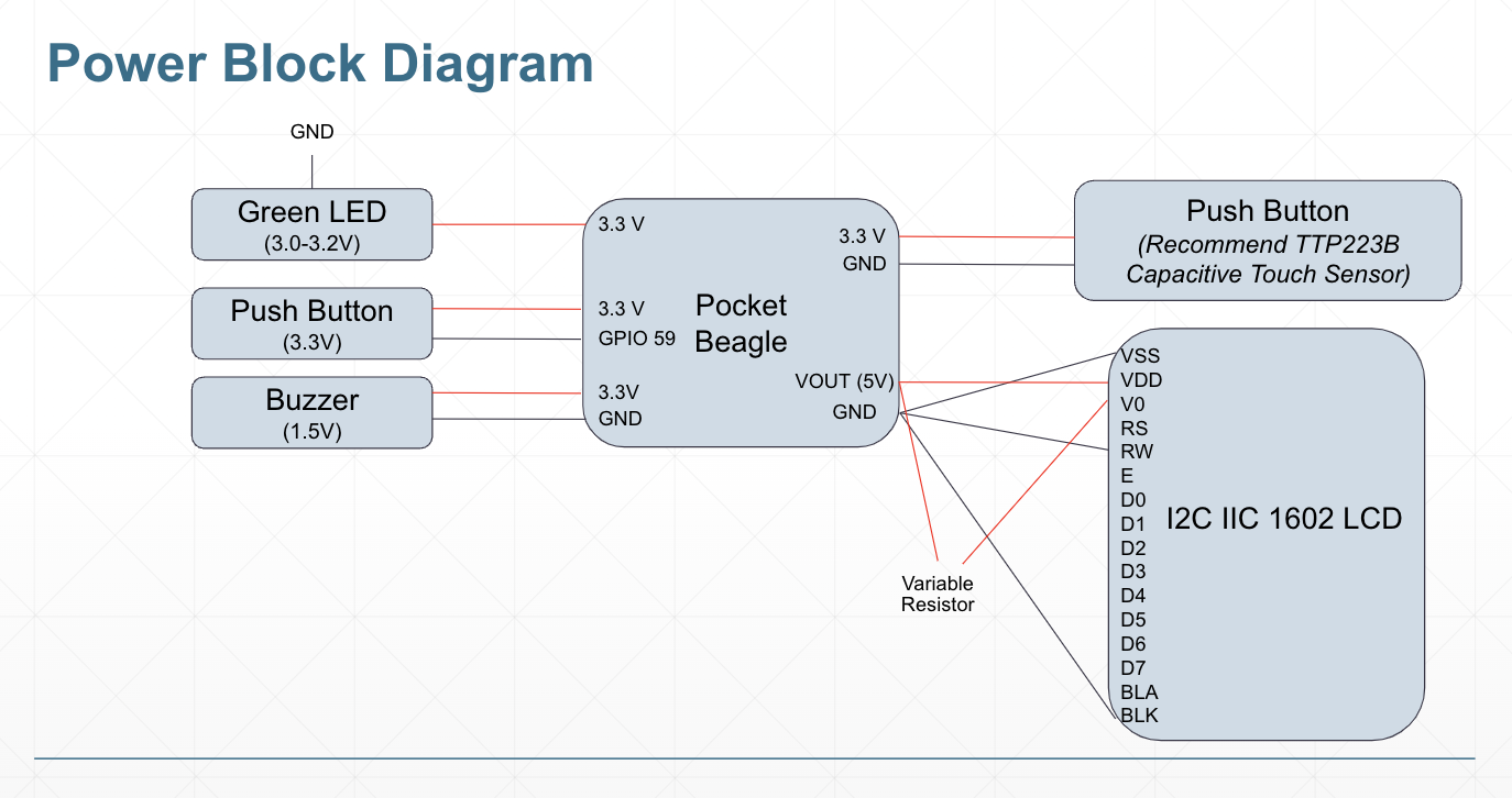
- Connect both positive (+) rails on the breadboard to the SYS 3.3V on the PocketBeagle (P1_14)
- Connect a positive rail on the half-sized breadboard to VOUT on the PocketBeagle (P2_13)
Integrate the yellow button
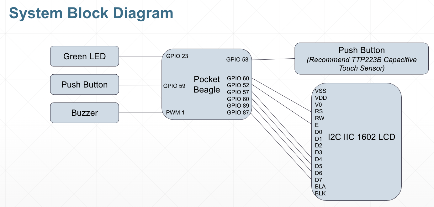
- Attach the button to the breadboard and attach a ground connection, as well as a pull-up resistor (1k ohm) connected to ground. Use a jumper wire to connect the button to the GPIO pin (GPIO59, P2_2), and this connection should be in parallel with the pullup resistor. (Fig 1)
Integrate the red button
- Attach the button to the breadboard and attach a ground connection, as well as a pull-up resistor (1k ohm) connected to ground. Use a jumper wire to connect the button to the GPIO pin (GPIO 58, P2_4), and this connection should be in parallel with the pull-up resistor. (Fig 2)
Integrate the LED
- Connect the LED to the PocketBeagle. Use a jumper wire to connect the anode (+, long lead) of the LED to the PocketBeagle GPIO pin (GPIO 23, P2_3), and connect the cathode (-, short lead) of the LED to ground. (Fig 3)
Integrate the buzzer
- Attach the buzzer to the breadboard. The buzzer has 2 connections: positive and negative. Attach the negative connection of the buzzer to ground, and use a jumper wire to attach the positive connection of the buzzer to the PocketBeagle PWM pin (PWM 1, P2_1). (Fig 4)
Integrate the 16x2 LCD Display (HD4478U)
- Solder male headers onto the LCD display to allow it to be attached on the breadboard.
- The LCD should be powered by connecting the pins VSS, RW, K to ground, and the pins VDD, V0, A to the VOUT (5V) positive power rail. V0 should be connected to the positive power rail through a variable resistor. The variable resistor can be tuned to alter the adjust the character's display contrast. Connections to the pocket beagle for data transmission involve connecting GPIO pins 60, 52, 57, 60, 89, 87 to pins RS, E, D4, D5, D6, D7 on the LCD, respectively. (Fig 5)
You have now completed construction of the device. (Fig 6)


Comments