

Hardware components | ||||||
| × | 1 | ||||
Software apps and online services | ||||||
| ||||||
Hand tools and fabrication machines | ||||||
 |
| |||||
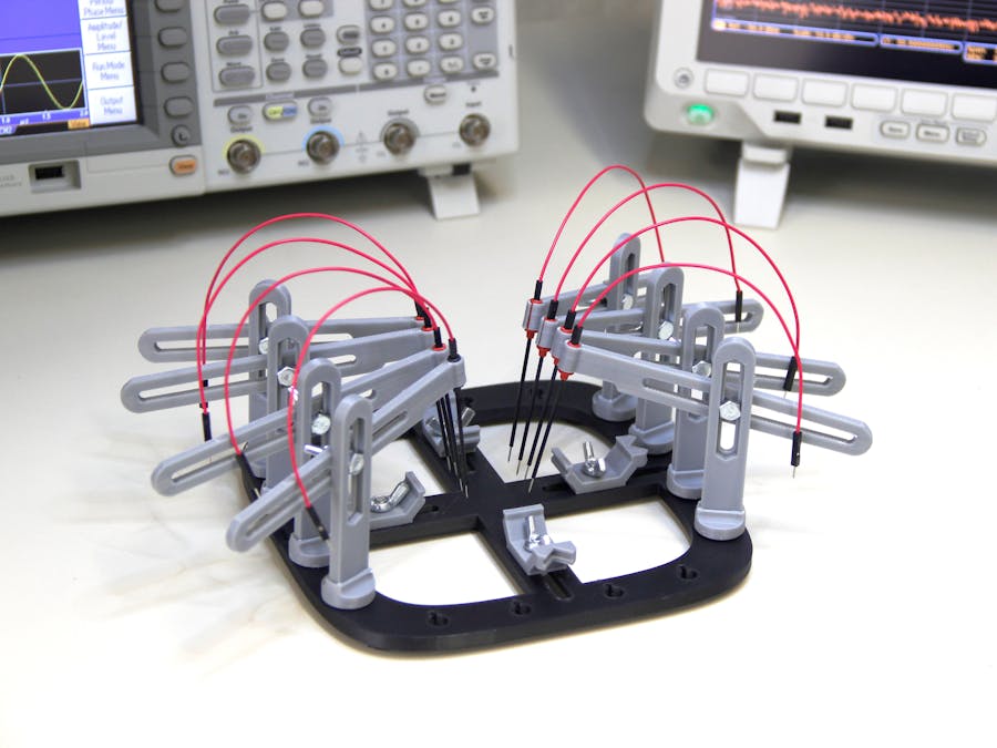
Anyone who does electronics knows how essential so-called Helping Hands (aka Third Hands) are in successful soldering. This “Ultimate” 3D printed version is great because you can print out and add as many arms as you desire.
Step 1: Print the partsThe first step is to print the base platform and pieces of the PCB Workstation with your 3D printer. Multiple types of bases are available, so you can choose the one that best suits your needs and your 3D printer dimensions. All the files you need for this project can be downloaded from my project page on Thingiverse.
Step 2: Mount the silicone bumpersI suggest to apply 5 silicone bumpers beneath the base piece, so it will be more stable on the desk. You can use bumpers with a diameter up to 20mm.
The central part of the base consists of 4 sliding pieces arranged in a cross along which can be moved the anchoring blocks to firmly keep the printed circuit board in place. The assembly of the PCB holders to the base piece requires some wing nuts (5mm) and Hex bolts (5×12 mm). The PCB holders have two faces, one for straight sides, the other for the corners of a printed circuit board. You can choose the right face simply turning the holder.
Fit the vertical crane arm into the hole of the rotating base support, then mount the horizontal crane arm using a wing nut (5mm) and a Hex bolt (5×12 mm).
Step 5: Install micro sprung probesThe horizontal crane arm ends with a clamp to fit a micro sprung probe
(http://uk.rs-online.com/web/p/needle-point-probes/0775726).
Now that you have almost finished your customized "PCB Workstation" perhaps you would like to add a magnifying glass, or a LED lamp, or even other accessories available from my original project "PCB Workstation with Articulated Arms" (http://www.thingiverse.com/thing:801279).
Step 7: Mount a PCB and start testing!
Comments