


Hardware components | ||||||
| × | 1 | ||||
| × | 1 | ||||
| × | 1 | ||||
| × | 1 | ||||
 |
| × | 1 | |||
Hand tools and fabrication machines | ||||||
 |
| |||||
| ||||||
| ||||||
Maker Faire Rome is coming and I would like to use the badge I got last year from SparkFun stand to do something cool. Time is running out and after I cleaned the dust from it I started to think how I could hack it and ended up on maintaining it's original use, a badge!
Just for the case that you don't know - that badge is an Arduino like board you can program like the original one, the only things different are some pins are already hooked up to the RGB led and the buzzer. Please refer to this page if you want to know more.
Hardware
Let's start, the first step is to desolder the letters from it, it's simple if you have the right tools.
When you finish you have to drill down 2 holes to mount the lcd, you can use your preferred tool, a Dremel is ok. Measure the distance from the holes on your display and mark it through the holes. Refer to the photo below where are mine.
ATTENTION! If you change the display you have to relocate the holes, look at the via and routes before drilling.
When you finish you have to prepare your display, you have to solder wires so - cut around 8 cm of wire for 4 connections, I've used AWG30 cable to pass through the holes and mask it. I don't connect the RGB LED but for every pin you have 2 holes in case you want to use them.
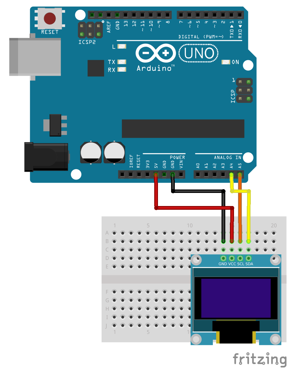
Now you have to solder lcd connections. I chose to get power from the ISP connector and I2C connection from A4, A5 pins, I have no choice ;) I've started with different colors cable for the lcd but ended up with all cables with the same color, red as you can see.
This is the connection diagram, sorry no badge's image on Fritzing but the pins names are the same.
You need also two M2 screws and nuts and a couple of spacers to mount lcd on the board. It's time to assemble all the parts together, here is how it appears from the back.
And here's from the front.
Programming
Now, you can turn off your soldering iron and turn on your computer. You need a FTDI programmer and the Arduino IDE, you will want to select the “Pro or Pro Mini (3.3V, 8MHz) w/ ATmega328” board option and the right serial port.
You also need two libraries from Adafruit:
- SSD1306 oled driver library for 'monochrome' 128x64 and 128x32 OLEDs
- Adafruit GFX graphics core library
Download and install them, when done open examples and choose ssd1306_128x64_i2c from the list. Press run button and let the magic happen.
Now you can modify the sketch, using examples as a start point you can write the text, images and shapes. Also, if you want you can play some melody from integrated buzzer, it's hooked up to D2 pin and you can start from Arduino examples sketch 02. Digital > toneMelody
ToDo
I would implement a communication option via Bluetooth or with an ESP8266. Also an accelerometer/gyro could be interesting to put a pedometer functionality so you could measure how many foot steps you do during the conference. Let me know if you have some hints. Light sensor, noise sensor or any kind of sensor and an SD Card reader to log data.
I hope to see you at the Maker Faire Rome, I would be very pleased to know that many of you have implemented this hack :)
SparkFun do you have a new badge for me this year?


_3u05Tpwasz.png?auto=compress%2Cformat&w=40&h=40&fit=fillmax&bg=fff&dpr=2)
Comments