The story
IntroductionHello everyone! Aim of this article is to explain how to make hexapod robot from scratch. Robot will be able to do various kind of movements and it will be able to balance its body on uneven terrain (keep body in horizontal plane). Let's divide whole project in 3 main parts:
and go through all 3 of them in details.
Mechanicalside
In order to assemble chassis of robot we used wood, organic glass and metal brackets. Let's start with the main frame, we used wood and laser cutter to make upper and lower parts of body and then connected them using metal brackets(black ones came with servo and silver ones we made by ourselves).
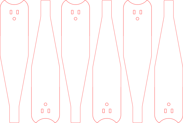
In order to make legs we connected 3 servos using brackets.One end of it is connected to mainframe and second end to organic glass. glass was also cut on laser and after it we bent it using heat gun(see process below), which gave it curved like shape. After bending it we connected two parts using wood cube and glue.
stepcheck
In order to detect when robot would touch on the ground during walking we added micro switch in every leg. Switch is connected on a custom made bracket. we drilled hole in the wood which connects 2 parts of leg and inserted metal rod and spring in it. Ground part of the rod is coated with a polyurethane (this increases friction on the ground and makes robot more stable) and upper part of rode is connected to micro switch and presses it when leg touches the ground.
Hardware
mainboard
we created circuit board which supports connection with esp32, mpu-6050 and servo motors. Servo's, which we have in this project, use half-duplex UART for communication with micro controller to achieve this type of communication we used 74hc126, transistor and few resistors(for NOT gate).
PowerCircuit board is receiving average 7.4V from the input which goes servo motors, after that voltage is reduced to 5v using dc->dc converter to supply other components of circuit(esp32, mpu-6050...). In order to deliver this power we used 4 3.7v lithium batteries and connected them to little charging board as it shown below:
batteries are connected to charging port and switch, which delivers power to main board.
SoftwareYou can use Arduino IDE or platform IO to compile and upload code to micro controller. Code is written in c++ and is divided in couple of libraries, which allows user to replace some parts of project by changing only corresponding library file. Note that code is still in work in progress so it is not perfect.
We used mobile phone to connect with esp32 using bluetooth application created specially for this project. It gives user ability to move robot and switch between few modes. It also outputs voltage present in servo motors which is good battery indicator (8.4v - fully charged, 6.4v - discharged).
Balancingrobot is using PID library to keep its body in horizontal plane, you can see what this process looks like below:
ConclusionThis project took me 1 year to make and it's still far from being perfect. It is still in work in progress so code will get updates. If any of you are interested in robotics you should find this article interesting, because it basically divides whole problem into much smaller problems which you can use individually for your projects. Write me if you will have any questions.
Good Luck!








Comments