



Hardware components | ||||||
 |
| × | 1 | |||
| × | 3 | ||||
| × | 1 | ||||
| × | 12 | ||||
| × | 12 | ||||
| × | 1 | ||||
Software apps and online services | ||||||
 |
| |||||
Hand tools and fabrication machines | ||||||
| ||||||
The Lazy Susan is a common tabletop accessory to provide diners with ready access to a number of shared food dishes. It is simply a rotating platform on which bowls of food and condiments are placed that can be easily rotated by the diners to bring a particular dish close enough to be served from. The Lazy Susan is typically made from two panels of wood (often), a base that sits directly on the table, with a rotating platform on top that accommodates the food dishes. The rotation is facilitated by a flat circular (turntable) bearing. Various sizes of Lazy Susan are available, to suit different sizes of table and numbers of diners. The Lazy Susan is commonly seen in restaurants that serve Chinese style food that is often provided in multiple small dishes to be shared by the diners.
The incentive to design and build an electronic Lazy Susan (the eLazy Susan) arose from the challenge to build one that does not require it to be manually rotated but would still allow the diners to rotate a desired dish to be close to their seating position. Many may suggest that this a rather silly thing to do, but it does present a range of technical challenges that might be interesting to solve. This project is about these challenges!
This project is not simply about producing an electrically powered Lazy Susan – there are plenty of these out there. These either rotate continuously or are controlled by a single on/off switch (who has control?). This one is aimed at being a more “intelligent” device and more diner focused.
The result of this project is a fully working eLazy Susan that may not be more useful than a simpler traditional one, but it might just inspire some new ideas about how such a device might be built and made to work.
A short video of the eLazy Susan in operation can be seen from here:
This short video shoes the optional power up display, then selecting an item and then rotating this to the diner.
Main Design PrinciplesFor the manual Lazy Susan the operational tasks are like this:
- A diner makes an observation about the dishes of food on the top platform.
- Using their hand, the diner rotates the platform so that the required dish is close enough to be dipped into and to move some food on to their own personal plate.
- Other diners (should) wait until the first user has completed serving themselves, before moving the platform to get access to their chosen food items.
- A certain amount of politeness and patience is required to allow all diners fair access to their desired food items.
The eLazy Susan should, as far as possible, facilitate these tasks. The question is then; how can this be done?
Firstly, the rotation of the top platform will require a motor of some sort. The initial thoughts on the motor were to consider a stepper motor. The stepper motor provides a direct way of controlling the amount of rotation (fixed number of steps per revolution and then perhaps geared to provide the required rotation speed of the platform). Due to the required low-profile of the eLazy Susan most (reasonably priced) stepper motors were considered to be too big. One low profile model was tested but it was found not to have enough torque to rotate the platform. A low-profile worm geared DC motor was then selected, one with a low profile and a high gear ratio. To enable the output rotations of the motor to be monitored, so that the required angular rotation can be provided, a motor with a rotational encoder was selected. The chosen motor (NFP-GF5560-180-EN) provides a gear reduction ratio of 1400:1, and with a rated torque of 25 kg.cm and it requires about 0.8 Amp at 12 Volts. It has a body height of just 19 mm (excluding the drive shaft).
Together with some additional electronics, the motor will require a power source. While a battery-powered option might be considered there would be obvious concerns about the amount of energy required to run the eLazy Susan for an extended dinner party (perhaps 3 or 4 hours). Losing battery power part way through the meal is not likely to be very popular. A large battery might be an option, but this is likely to be too large to fit inside the eLazy Susan package, and it would probably need to be located externally with a power cable. The alternative is a low-voltage DC power supply from an AC power adapter. This would require a power cable to be provided to the table (low voltage) with the power adapter plugged into the normal AC power. This option was judged to be viable as it would provide reliable power without interruption, and it is also quite safe.
While the motor can rotate the top platform, there needs to be some way for the diners to signal their requirements. In particular, where they are each seated and which dish of food they would like to have access too. The obvious solution here is to provide a set of physical push buttons (or similar). These buttons will be placed around the base of the eLazy Susan so that they are in a fixed position relative to each diner, so that each diner has their “own” button. This button device needs to be reliable and provide some obvious haptic feedback so that the diner gets an immediate indication that their button press has been registered (more problematical with touch sensitive sensors).
When pressed the diner needs to know that the press was actually registered. To supplement the button-press feedback, it was decided to add a LED light (at the button) that would turn on when the button press was registered. This provides an additional, and confirming, feedback signal.
The rotating platform is, of course, round and each diner will have immediate access to just a small part of this perimeter. It was therefore decided that there should be 12 buttons around the eLazy Susan. The number 12 is, perhaps, a little arbitrary and maybe a fewer or a larger number of buttons would be just as useful. The number 12 was chosen due to association with clocks. Everyone (well most) is familiar with traditional analogue clocks and their 12 intervals (around a circle), so seeing a pattern of 12 buttons will be a familiar sight to many diners, and will not pose issues about the number of buttons, their accessibility etc (this is a working hypothesis!).
So, we now have 12 buttons, each with a LED to indicate that the button was pressed. But we need more facilities to make the eLazy Susan work usefully. The diner needs to be able to select the required dish of food and then rotate the platform around to their position. There are two possible options considered here:
- The diner simply holds their button down to signal to the motor to turn on and start rotating the platform. The diner releases the button when the required dish is close enough to access it. One complication with this approach is that we may wish to decide the direction to rotate the platform to minimise the rotational time required. If the rotation is always on one direction, then moving a dish from just to the left of the diner might require rotating the platform almost a full turn. One strategy might be to change the direction of rotation on every second button push. So that, if a diner finds the platform is moving the “long way around”, then this direction can be reversed by simply releasing the button and pressing it again.
- Provide the diner with an explicit procedure to select a dish, then automatically rotate the platform to where the diner is seated. This process might be more succinct (and more interesting!). This approach requires some additional information to be provided by the diner. There are three stages in such a process: firstly, to identify the diner’s position; secondly, to identify the desired dish position; and finally, to rotate the platform to bring the dish to the diner. To implement this process, we can use the LEDs around the base to select the required dish by asking the diner (who has already identified them self with a button push) to tap again on the button, so that at each tap the next (say clockwise) LED is turned on until the LED closest to the desired dish is on. We now have two pieces of information: where the diner is located, and where the desired dish is located. With this information, the diner can simply press and hold (for a short time) the button to indicate that the motor should start rotating the platform. Once the rotation has commenced the diner releases the button, and the platform continues to rotate until the selected dish is at the diner’s position. In addition, with this method, we also know in which direction to rotate the platform to bring the dish to the diner in the shortest time.
The value of either of these two approaches is open for evaluation and testing. The LEDs (in both approaches) are providing important information for the diners, and in the second approach two different functions are implied (selecting the diner and selecting the dish of food). This suggests that it might be useful to have (at least) two different coloured LEDS. This is possible using tri-coloured LEDS (RED, GREEN and BLUE) so that various colors can be provided from a single physical LED device.
It is now clear that to achieve either of these operational modes some advanced control functions need to be provided; and most probably from a microprocessor that can interpret the button pushes, display the LEDs and control the motor to rotate the platform. For this design an Arduino family microprocessor was chosen due to its low cost and accessibility to a large range of software and technical support. Choosing the precise model depends on a number of factors, including:
- To manage and control a suitable driving motor: a wide range of both stepper and DC motors can be used with appropriate and readily available driver modules. An L298N driver was used here, one that can drive either a stepper motor or a DC motor.
- To manage 12 buttons and 12 tri-colour LEDs a total of 48 digital I/O ports are required, and some more IO ports will be required to manage the motor (stepper or DC). This means that it will be necessary to provide a number of digital I/O port expansion modules, in fact 3 x 16 port extender modules, (the Adafruit PCF8575 I2C module) were used.
- As it is proposed to provide optional operating modes (like the dish selection process described above) it would seem useful to be able to change the operating mode settings while the eLazy Susan is in use (and away from the programming environment). This implies a need to communicate with the on-board microprocessor from some external device(s). This might be done with a number of physical switches, or even some form of a control panel. The obvious choice was to use a telephone with Bluetooth technology. Bluetooth is available on most phones and is easily configured for a one-to-one (Client-Server) connection. With a matching App (on the phone) it is then possible to change all the available settings on the eLazy Susan on the fly. WiFi technology could also be used with the Arduino providing an access point for a phone-based (say) connection.
With these requirements in mind an Arduino UNO R4 WiFi was the chosen microprocessor. This model is inexpensive, well supported in the on -line forums, and provides all the required capabilities, including Bluetooth.
Packaging the eLazy SusanWhile many Lazy Susans are presented as being purely functional with little attention to their presentation, this project aims to produce a device that might add to the decoration on the dining table. It is made from Jarrah (Eucalyptus marginata), a locally available timber in Western Australia, and now considered to be a threatened species. It has a characteristic red-brown colour, it is hard (Janka harness of 8270 N) and heavy (typically 820 kg/m3). It is (or perhaps has been) popular for making fine furniture and due to its durability was commonly used for below ground and marine structures. The finished eLazy Susan is shown in Figure 1, showing the 12 buttons with their LEDS around the base, and the 12 VDC power supply plugged in.
The eLazy Susan should not be too tall as the contents of the onboard dishes of food need to be visible to the diners. But it will need to contain a range of devices (motor and electronics). There is thus a challenge to achieve both of these goals. The chosen physical design cross section is shown in Figure 2.
The overall diameter is 470 mm, and this is suitable for a modest table size, and the total height is about 54 mm. The eLazy Susan is made from three sections of wood, each 19 mm thick. The base is made from two parts, the bottom section and the annular shaped middle section. This part supports the turntable bearing. The top rotating platform completes the package. Each of these parts is machined out on their insides to accommodate the various parts. These parts were machined using a CNC router.
The top platform is supported on a turntable bearing, and centred with a vertical axel that is held in a bearing placed in the bottom part. The bottom and middle sections are machined separately so that channels can be cut into the top of the bottom section to accommodate the wires to the buttons and LEDS that are placed around the edge of the base. They are then glued together. The middle section has a lip around its top that fits into the underside of the top platform. This lip is intended to prevent any liquids spilled onto the eLazy Susan flowing into the internal space.
The base section is also further machined out to accommodate the DC motor, as this is the most difficult part to fit into the internal space. The top panel is driven from the DC motor using two (timing) gear wheels with a matching toothed drive belt. The central gear is fixed to a shaft that is held in a bearing in the bottom section. The top panel is held by four driving pins fitted to this gear (see Figure 5).
The other components (Arduino microprocessor, motor driver, and the three digital port extender modules can just fit into the internal cavity, together with all the wiring also. The internal space is very tight, as will be seen later in some photographs.
Making the height of the eLazy Susan greater would have helped the construction greatly, but at the expense of having a rather high platform for the diners to navigate.
A major challenge with this design is to manage the fitting, and removal, of the top platform as the various parts are fitted and tested, and this task needs to be done often. The top platform is designed to simply sit on to the central driving gear, with a little jiggle to get it to fall onto the holes made for the driving pins in the gear.
A plan section of the eLazy Susan is shown in Figure 3, showing:
- The position of the motor and driving pulleys.
- The position of the Arduino microprocessor.
- The slots machined into the base section for the wires to the push button switches and the LEDs
- Two channels in the base section for the cables to provide a USB cable extension from the microprocessor (for programming), and one for the 12V DC power supply to the outside of the package.
- The remaining space is taken up with: the three digital I/O extender modules, the motor driver module, and a DC-DC buck module (12V > 5V) to provide supplementary 5V power.
The chosen DC motor is shown in Figure 4. This is a low-profile motor (the main body is just 19 mm high). In this design it was decided to drive the top platform with a belt on two timing gears to provide a little flexibility in the drive system as shown in Figure 5. Note that a small tension idler is used to adjust the tension in the driving belt. In retrospect, however, it might have been better to place the motor (shaft) in the centre and directly drive the top platform. This motor (NFP-GF5560-180-EN) requires a DC motor driver, to control its speed thought a PWM signal. It also provides an encoder that provides a number of pulses per revolution that can be used to count, and set, the number of required motor revolutions to achieve a required fractional revolution of the top platform.
The other major component to fit into the package is the Arduino microprocessor. The UNO R4 WiFi is quite a low profile, so a screw mount hat was added to make the wiring a little easier. This fitted into the internal space (just).
Mounting the various components into the wooden package is not generally a problem with the use of small wood screws. There are, however, two problem areas.
Mounting the 12 sets of switches and LEDS around the base requires special care. These are exposed to the diner so careful design is required. This was achieved with a 3D printed holding bracket as shown in Figure 7.
This small holding bracket was printed in black PLA. It has a hole for the push button switch, and an up-stand with a hole to allow the tri-colour LEDs to be press fitted from underneath. This holding bracket fits onto the base with the wires from the switch and the LED pulled down through the hole and the channel, and into the base. It sits neatly on the base, perhaps with a little PA glue to hold it in place as shown in Figure 1.
The other concern is the mounting of the motor relative to the central shaft. This was done with another 3D printed bracket as shown in Figure 8.
In this bracket, the DC motor is mounted to the underside, and the right-side extension fits over the centre shaft to fix the motor at the required distance from the central shaft. The motor is mounted to the bracket with M3 bolts, then the whole unit screwed to the wooden base.
Wiring the eLazy Susan is challenging as a lot of connections are required. For each of the 12 button/LEDs, there are 6 wires to be connected:
- Switch – 2 wires: 5V and a Digital Input
- LED – 4 wires: Anode and the RED, GREEN and BLUE cathodes as digital Outputs.
This requires 12 digital inputs and 36 digital outputs that are connected to the three PCF8575 I2C port extender modules (providing 48 ports over the three I2C modules). On the Arduino R4 UNO WiFi these can be connected to each other - (chained) using the provided STEMMA QT connectors that are quite convenient to use. The wires from the switches and LEDS must be provided as shown in Figure 9 connecting to each of the 48 ports on the three PCF8575 modules.
The formal circuit diagram (part only) is shown in Figure 10. Here we see the connection of the three I2C port extenders to provide the connections to the 12 buttons (as INPUTS_PULLUP) and the 12 tri--coloured LEDS (using 3 x 12 OUTPUT ports). Each of the LED connections to the output ports also has a series resistor (200 – 400 Ώ, tuned to get the luminance of the three colours to be about the same).
The software required for the eLazy Susan is, of course, central to its successful operation. The complete code is attached and the key elements are described here to sufficiently to appreciate the detailed design. There are three parts to the required software:
- A package to run on the Arduino UNO that directly interprets the button pushes, displays the required LEDs and runs the motor as required.
- A Bluetooth (BT) server on the Arduino UNO to talk to the BT App on a telephone and to update parameter settings as required.
- A BT App on a telephone to allow all the running parameters to be viewed and changed.
The Arduino UNO R4 WiFi supports BLE (low energy BT) and this is compatible with using a telephone as a client.
For this project, it is anticipated that there will be a single eLazy Susan with a matching BT App so it is not necessary to build a more general purpose App that can connect to one of several eLazy Susans. It will be a unique one-to-one connection. With this in mind it is only necessary to define a set of unique UART Service UUIDs (128 bit identifiers) that are known to both the Arduino and the BT App on the telephone. There are several on-line services that can generate unique UUIDs for you. For this application we need three UUIDs: one for the UART Server, one for the Receiver channel (RX) and one for the Transmitter channel (TX).
The operational modes for the software, as implemented, are as follows:
Select Mode (ON/OFF): If Select Mode is ON then the diner identifies themselves with a button push, then selects the dish required with multiple button pushes, then activates the motor with a button hold to rotate the platform from this dish back to the diners position. If Select Mode is OFF, the diner presses and holds the button until the top platform rotates around to bring the required dish to the diner, then releases the button. If Select Mode is ON then LED#0 flashes BLUE every second, if it is OFF it flashes twice every second so that the currently set mode is visible.
Auto Mode (ON/OFF): If Auto Mode is ON, the top platform automatically rotates a fixed amount every set time interval. The rotation is set at 5/12 of a full rotation and the time interval is 2 mins. This automatic rotation will bring every dish in front of each diner every 16 mins without any diner intervention. If Auto Mode is OFF, then there is no automatic rotation of the platform.
Startup Mode (ON/OFF): The normal Startup Mode is ON, then on power up a short pattern of BLUE LEDs is displayed to welcome the diners to the table. If OFF no startup display is shown.
The operating modes must be each implemented in the code and there might be many other possible (and interesting) operating modes that could be explored.
Button, LED and Motor ControlThe operation of the eLazy Susan is controlled by button actions; there can be button pushes (press then release in a short period of time) and button holds (push, hold, then release after a longer period of time).
The distinction between these two action is the duration of the button hold. After some experimentation is was found that if a button was held down for more than 500 msec then this would be classed as a “Hold”, if shorter then a “Press”. It is also desirable that a “Press” selection is detected as quickly as practical, and not waiting for the full 500 msec period. To achieve this, when a button press is detected:
- A new watching loop with a maximum of 50 cycles is created with a cycle time of about 10msec.
- If the button is released before the loop terminates then a “Press” is recorded and the loop exited, else
- If the loop terminates then a “Hold” is recorded.
This gives us the ID of the button that was pushed and whether is was a simple push or a hold.
To begin, we assume that an Idle state exists (i.e. the eLazy Susan is ready for action), and if Select Mode is ON then:
- If a button push is detected then the matching LED is displayed as RED (the diner has registered their interest).
- The next, and subsequent button pushes select the next position around the base in a clockwise direction, displaying a GREEN LED at this position at each push.
- When a button Hold is detected then we know which dish is desired by the diner, the motor then activates and rotates the platform around to the diner. The direction of rotation can be either clockwise or anticlockwise. The direction is chosen to minimise the time required.
- To rotate the platform the required angle, the number of pulses from the motor encoder are recorded (from the time the motor starts) and the motor is stopped when the required count is identified.
- The motor encoder pulses are counted in an Arduino interrupt function. For the motor used there are about 3200 encoder counts to rotate the platform 30ᶛ (or 1/12 of a revolution).
- The diner’s LED and the dish selected LED are then turned OFF.
- If the diner does not complete the selection process within 5 secs, the Selection process is terminated and the idle state is resumed.
If Select Mode is OFF then:
- If a button Hold is detected then the matching LED is displayed as RED.
- The motor is turned on (clockwise, or anticlockwise) and the platform starts to rotate.
- When the button is released, the motor is turned OFF as well as the LED.
- On each new button Hold, the direction of the motor is reversed. This allows the diner to change the direction of rotation; if it is going to take the long way around.
The following pseudo code (in loop()) provides an overview of the required code to detect button pushes and holds and, depending of the set modes, cause the platform to rotate the required amount.
// get pressed button number (0 –> 11)
if( but >= 0)
{
  If(!buttonHold)   // button clicked only
  {
    If(selectMode == 1)
    {
    // button pushed by diner, display RED
      while(wait)   // for a few seconds
      {
      // get press button
       if(!buttonHold)   // button click
       {
       // select next position on left
       // display GREEN
       }
       else  // button hold
       {
         // calculate required rotation (+/-)
         // rotate platform
       }
     }

   }
   else  // selectMode == 0 – manual move
   {
    // display LED RED
    // reverse motor
    // turn motor ON
   }

}
// turn motor OFF     // button must have been released
// turn all LEDS OFF
If(autoMode  == 1)
{
  // if time since last move > set interval)
  // turn on motor for required number of encoder steps
}The default operating modes are saved in the EEPROM memory of the Arduino UNO microprocessor. If they are changed at some point in time (by using the BT App) then the new values are updated in the EEPROM, so becoming the default values for the next time the eLazy Susan is used (powered up).
Changing these modes is done on a BT telephone-based App (see below) with a BT server on the Arduino microprocessor.
To begin, the steps to establish a BT server are like this:
- Using the required Arduino library: ArduinoBLE.h, that support the low energy BT protocols.
- Creating the required UART services using the UUIDs as created above, like this:
// Nordic UART Service UUIDs (commonly used with App Inventor BLE extensions)
#define UART_SERVICE_UUID "698bd1da-4efb-48b5-8a55-e6c40894fd18"
//iPhone -> Aruino
#define UART_RX_CHAR_UUID "f3ed0622-c79d-4aa7-975d-4ce2abdeec08"
//Arduino -> iPhone
#define UART_TX_CHAR_UUID "7aa97144-3ae7-4454-a5ee-e5330875ee94"
BLEService uartService(UART_SERVICE_UUID);
// RX: App → Arduino
BLEStringCharacteristic rxChar(UART_RX_CHAR_UUID,BLEWrite |
                             BLEWriteWithoutResponse,64);
// TX: Arduino → App
BLEStringCharacteristic txChar(UART_TX_CHAR_UUID,BLENotify,64);
Inititalize the BT Server in setup(), by providing the server names, adding the TX and RX services and finally advertising the service to the world.
BLE.begin()
BLE.setLocalName("LSman-L");
BLE.setDeviceName("LSman-D");
BLE.setAdvertisedService(uartService);
uartService.addCharacteristic(rxChar);
uartService.addCharacteristic(txChar);
BLE.setAdvertisingInterval(320);
BLE.addService(uartService);
BLE.advertise();
Serial.println("BLE UART service advertising...");- The BT client may or may not be transmitting it's interest at any point of time, and this state may change over time. So, in the main loop(), we need to check to see if the client has woken up and wants to talk. This is done as follows:
- Check to see if the Client is connected:
BLEDevice central = BLE.central();
While (central.connected())
{
// Read/write operations
}- To read data from the client (as a String in this case, note that various data types are available)
String incoming = (rxChar.value()).c_str();- To write data to the client (as a String in this case)
txChar.writeValue(message.c_str());- If the BT App is not connected, or disconnects after a period of time then the program on the Arduino reverts to checking button states. This means that while connected to the BT App, the buttons on the eLazy Susan are not active. This is a reasonable approach providing the BT App does an automatic disconnect if it is not used for a short period of time (say 30 secs).
- When connected to the client, the LED#0 on the eLazy Susan is turned on (BLUE), and it stays on while the connection is active. The LED is turned off when the connection closes. This is useful for the diners to know that the eLazy Susan is otherwise busy.
- The complete loop() can be summarised as follows, including the handling of the button pushes, and so that the BT connections is checked on each cycle and if connected it is processed until the connection is closed before proceeding to check for more button pushes:
void loop()
{
   ...
   while(central.connected()
   {
   // handle BT communications
   ...
   }
   int but = scanButtons();  // scan for button push/hold actions
   // handle button push/hold actions
   ...
   delay(10);
}Developing the BT App for the telephone does provide some additional challenges, especially for those not normally working in the App development business. The first step to is to decide if the App is to be targeted at the iPhone and/or Android markets. While both are possible, developing Apps for the iPhone poses some additional complexities with regard to security and the permissions to load an App into the iPhone. It is necessary to become a registered Apple Developer, and this involves fees. Android App development is much more straight forward as the security controls are left up to the user (when loading the App onto the phone). For the amateur developer, therefore, this is a more straightforward way to go (at least to demonstrate the principles)
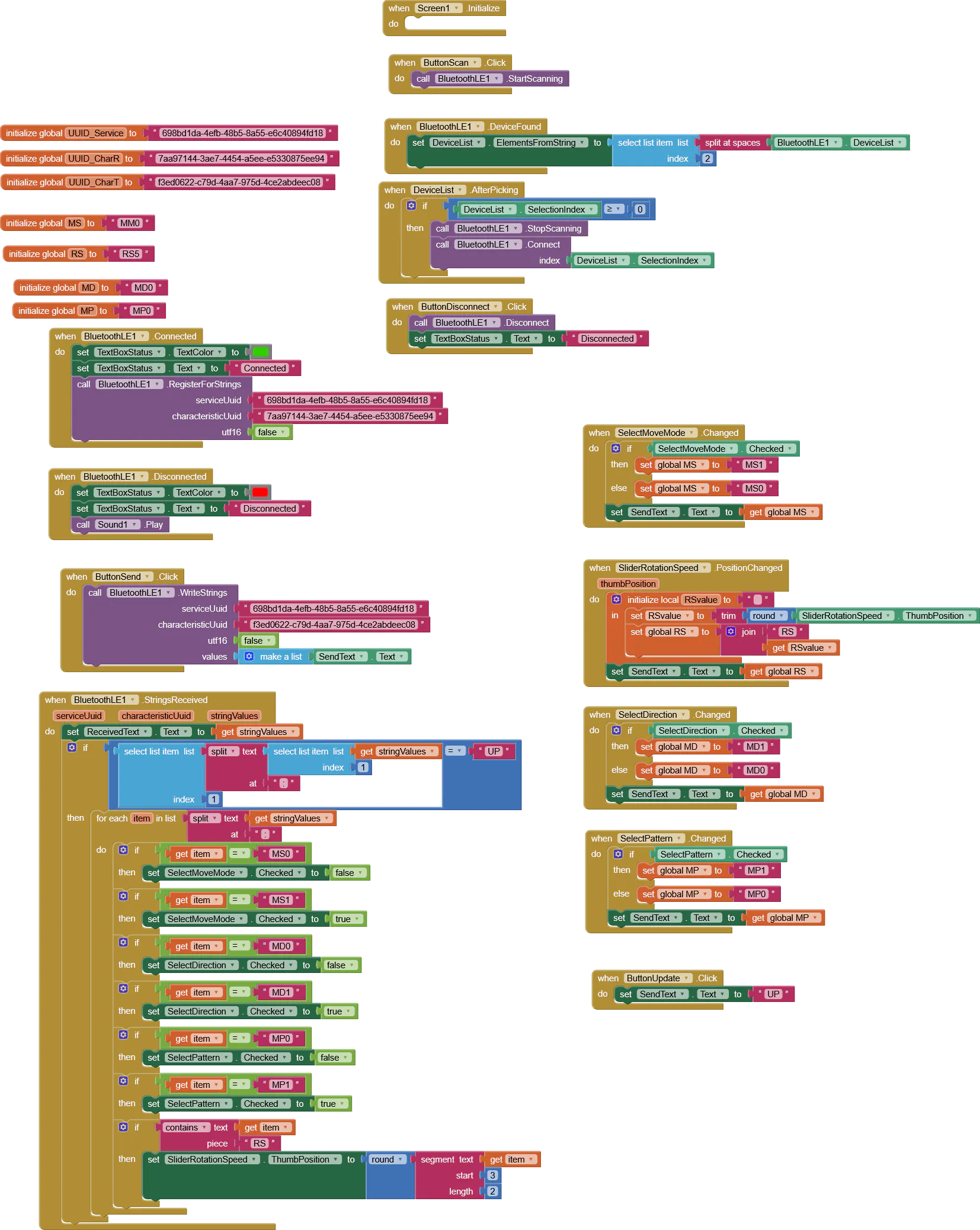
The tool used to develop the App for this project was MIT App Inventor (free to use). This is an online development environment that is based on a graphical block-based programming language. App Inventor provides a wide range of capabilities to build Apps for either iPhone or Android. The development is done in an online mode. Installers can also be created that can be used to create a runtime executable to run on the phone (iPhone or Android). The complications come when trying to install an App on the iPhone. The Android option is quite straight forward and is used here. App Inventor does provide a BLE library, as an optional extra, that is required to develop a client to talk to the BLE server on the Arduino UNO.
App Inventor runs in an online mode, where the program is created though a browser to select and assemble the required program blocks. With the App Inventor App installed on the phone, the created App can be downloaded and interpreted on the phone for testing purposes. Once the App is working, an installer can be created (iPhone or Android) and down loaded to a local PC/Mac machine for installation as a runtime App on the phone. In the Android environment this process is quite straight forward giving a fully runtime App on the phone.
App Inventor provides all the capabilities to build a user interface like the one shown in Figure 11. This shows a working (but quite simple) user interface to connect to the eLazy Susan, and to read, and set, the various mode options. At this stage it shows some debugging information, that might be removed at a later stage.
The first task for the App is to scan for available BT devices. This is done by selecting the <Scan> button option (that initiates a scan). The <Show Devices> button then provides a (popup) list of found devices in which we look to the one named “LSMan-L” as preset in the Arduino code, as shown in Figure 12. Other locally available BT servers might also appear here.
If this device is selected, then the state of the App becomes “Connected” to the Server as shown in Figure 13. And, hopefully also on the Arduino, a connection is made and the LED#0 will be set to be ON BLUE.
To begin with, the Client may not know what the current mode settings are on the eLazy Susan (unless they are also saved on the phone). These are found (by sending a request to the Server) by pressing the <Update> button, that then prepares an “UP” (for update) command to the server. This command is first displayed in the “Send” field, then sent to the Server from the <Send> button. An acknowledgement (from the Arduino) will be received in the “Received” field and the actual values updated (Select Mode, Auto Mode, Pattern Mode and Rotation Speed). This sets the App to the current Mode states from the eLazy Susan.
The “Send” and “Received” field are displayed here for debugging purposes, they might otherwise be hidden.
To change the Mode state for the eLazy Susan, the user of the phone:
- Selects the required check box, or slides the rotation <Speed slider>.
- The relevant command will then appear in the “Send” field.
- Press the <Send> button to send the command to the server, and the Server will handle this request.
- An acknowledgement will appear in the “Received” field
To disconnect from the Server, use the <Disconnect> button, the status will then change to Disconnected. To reconnect, use <Scan> then <Show Devices> and choose “LSman-L” again. If there is no action on the phone for 30 secs, then the connection is automatically closed so that the eLazy Susan is available for use.
SummaryThe challenges in this project were mainly relating to designing and making to work the physical parts of the eLazy Susan. There are a lot of bits and pieces to be inserted into the package that is naturally restricted in size (especially its height).
The electronics and programming were less of a problem, once the BT connections were sorted out. Creating the BT Server on the Arduino was the more challenging job to do. The coding of the App was, in fact, much more straight forward as App Inventor proved to be relatively easy to use, and with a little practice the tasks of finding and fitting the right, and compatible, blocks together become easier.
With the basic configuration sorted then one can imagine that there might be other operational strategies that could be explored to provide the diners with even more useful functionality.


Comments