

Hardware components | ||||||
 |
| × | 2 | |||
| × | 1 | ||||
| × | 1 | ||||
| × | 1 | ||||
 |
| × | 1 | |||
| × | 1 | ||||
| × | 1 | ||||
| × | 1 | ||||
| × | 1 | ||||
Hand tools and fabrication machines | ||||||
 |
| |||||
|
| |||||
Melty Brain combat robots are rare types of full-body spinners in which the entire robot rotates about its center axis. The drive wheel(s) create the spinning motion, and the robot translates by turning the drive motors off for half of the rotation, creating a net velocity vector. While most combat robots have two separate systems - one for the drive train and one for the weapon system - a melty brain combines these into one system, eliminating the need for weight budgeting and ensuring that all of the robot's mass goes into producing rotational kinetic energy. Thus, they can potentially be many times more powerful than other kinetic energy robots (shell spinners, bar spinners, etc.) in the same weight class. Like all kinetic energy weapon robots, melty brains seek to incapacitate their opponents by impacting them repeatedly at high velocity.
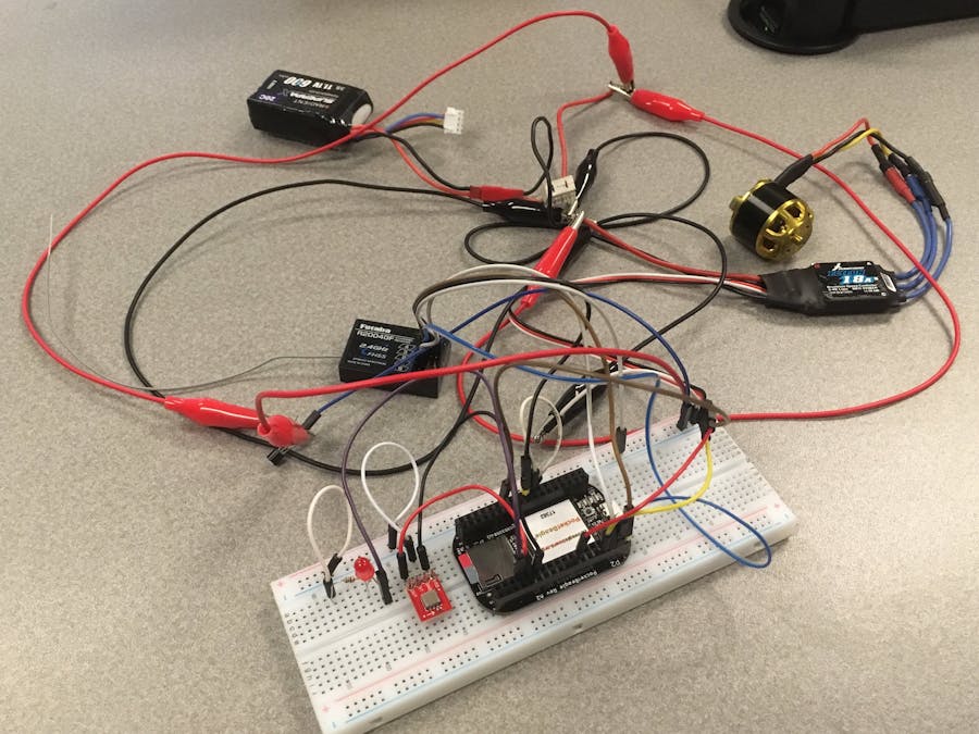
Project OverviewThis melty brain circuit is designed to power a 3lb robot (AKA a "Beetleweight"). The robot receives three signals from the transmitter - forward/backward, left/right, and throttle. The processor onboard the PocketBeagle then computes the voltage to be sent to the motor over time. If the robot is instructed to simply increase its spin velocity, the motor will be fed a constant supply voltage. If it is directed to translate, the PocketBeagle instructs the motor to turn on and off at precise locations in its rotation cycle, producing a net velocity vector in the specified direction. For example, if a counterclockwise spinning robot is to move forward, the motor(s) will turn off for the half of the revolution in which they are momentarily traveling backward.
An accelerometer provides the necessary data to determine the exact time intervals required between on/off switches. An LED lights up whenever the robot is pointing in the desired direction, which allows the driver to know which direction the robot is facing. The whole system is powered by a 3S LiPo battery, and there is also a main power switch for safety. A 5V regulator ensures that the PocketBeagle and receiver each receive their recommended input voltages. The PocketBeagle controls each device with standard GPIO pins. The final version of the circuit will be constructed with standard 18-22AWG wire. However, for this prototype, it is sufficient to use a breadboard and accompanying jumper wires for signal connections and low voltages (5V or less).
Next Steps- Update the wiring to reflect the final combat-ready version
- Build a test chassis
- Run tests with test chassis

Melty Brain Code
C Header File// "Open Melt" - Open Source Translational Drift / Melty Brain Robot
// WinAVR-20090313
// Copyright Rich Olson - rich@spambutcher.com
// Originally developed for "Melty B" / "Melty Beetle" combat robots
// Project homepage: http://www.nothinglabs.com/openmelt/ (see for additional documentation)
// Thanks to Richard Wong for his research on brushless motor support
// Build 1 - 12/08/09
// Build 2 - 12/12/09 (minor documentation updates, changed the default value for led_adjust to something more useful)
// Build 10 - 01/12/10 Redid LED / motor timing code to use timer - 3us resolution as opposed to 1ms - tracking looks "cleaner"
// Moved a bunch of variables from long / int to float
// Consolidated both motor cycles into single routine
// Added code to prevent bot from getting "stuck" in RPM count if throttle is high
// Added "smoothing" to RC data for left/right and throttle
// Tweaked code for calculating throttle percent
// Other minor tweaks
// Random notes updates
// Build 11 - 2/18/10 Documentation update to reflect that Sparkfun's ADXL193 board has been tested / verified to work (no code changes)
// Build 12 - 1/07/11 Fixed minor logic error - should not effect performance
// Build 20 - 8/25/11 Integrated brushless support, removed support for old-style "non-B" Baby Orangutan, documentation updates (be sure use_pwm_esc is set correctly!)
// Project added to github on 3/12/13
// Pre-build: Verify pin assignments are for correct for "B" style Baby Orangutan
// Some rights reserved:
// Attribution-Noncommercial-Share Alike 3.0 Unported
// Details at: http://creativecommons.org/licenses/by-nc-sa/3.0/
// - You are free to use / modify this code for non-commercial projects
// - Commercial projects require specific permission from the author (this includes any redistrubution of the code in exchange for money)
// - But you have to give credit to the original author
// - Contact the author if you're interested in commercial use
// - If you're using this code for a project - please let the author know about it! (not mandatory)
// - There are almost certainly some bugs / errors in documentation
// - No support is implied (but - if you email the author - you might get a helpful response)
// WARNING / DISCLAIMER:
// YOU MUST READ THIS!!!!
// This code is provided for your use without warranty
// It is not advertised as being for any specific use
// The author is making this code available for your intellectual curiosity
// If you should choose to attempt compiling / deploying it - you are placing your life in danger!
// Semi-autonomous systems can be extremely dangerous
// You should assume at any time the robot when powered may "spin-up" (even if not instructed to by the operator)
// and cause corresponding damage / injury / death.
// This may be caused by any number of errors in implementation - however - may have no apparent cause at all.
// THIS IS A REAL CONCERN - MOTOR "GLITCHES" HAVE BEEN OBSERVED ON SOME PLATFORMS DURING TESTING - THAT HAVE NEVER BEEN FULLY UNDERSTOOD / EXPLAINED
// In addition - this code may have "bugs" that may further endanger anyone attempting to utilize it
// A 1lbs spinning robot is likely capable of causing significant injury
// Larger robots may very plausibly kill someone.
// SPECIFICALLY - BUILDING A TRANSLATIONAL DRIFT ROBOT OVER 3 LBS IS ONE OF THE MORE DANGEROUS THINGS I CAN IMAGINE DOING
// Anyone creating a larger robot (over 3lbs) should consider implemeting secondary fail-safe systems not mentioned in this document
// (ie - an independant system capable of killing power via a secondary receiver / remote)
// It is reasonbly argued that a larger bot should have a "pull-down" resistor on motor-drive pin(s) to further reduce chances of an unwanted spin-up
// Again - this code isn't being advertised as being suitable for -anything- - but - especially not a heavier than 3 lbs robot.
// If you are intent on placing your life in danger by building a semi-autonomous robot
// you may want to consider building a less-dangerous (under 1lbs) test-platform to better understand how things work
// The author is not responsible for any damages / injury / death resulting from use of this code
// Your life is in your hands - don't sue me.
// Hardware List:
// MCU Board: Pololu (pololu.com) Baby Orangutan / B-328 Robot Controller (Atmega 328 / 20MHZ crystal)
// Accelerometer Option 1: Freescale 200g MMA2301Eg (Mouser.com)
// Accelerometer Option 2: ADXL193 (available pre-mounted from Sparkfun - http://www.sparkfun.com/commerce/product_info.php?products_id=9332)
// "Config Mode" can account for minor differences in accelerometer specifications without changing constants (it's all linear math)
// NPN Darlington transistor(s) to drive motor(s)
// MJ11032G - moderate power - about 20 amps @ 10v (see data sheet for more info)
// TIP120 (Radio Shack) - useable for very small test platforms
// Jaycar SY-4086 - Solid state relay - 100 amps / 32V (requires an extra diode / minor wiring differences - read the spec sheet closely)
// Some kind of motor(s)
// Either 1 or 2 motors may be used (maybe more if you get creative)
// A heading LED (up to 3 Watts)
// 5V Regulator (see note below)
// Some resistors (detailed in wiring notes)
// General Notes:
// This system uses an accelerometer to calculate the rate of rotation based on G-forces around a given radius.
// That data is then used to light up an LED once per rotation - giving the appearance of the "front" of the robot.
// The user can adjust the heading beacon by moving the remote control left or right.
// To move - the system turns a motor on when that motor is in the correct position to result in a net movement the direction the robot is intended to go.
// For example - if the heading beacon is on approximately between 10 o-clock and 2 o-clock it indicates movement will be towards 12 o-clock.
// Pushing "forward" on the remote causes the robot to turn on the motor(s) between 6 and 12 o-clock each rotation - the net direction of travel being towards 12 o-clock.
// When the robot is desired to be standing still - the system alternates when the motor(s) are powered to cancel out any translation.
// This description is somewhat of a simplification - see video footage at http://www.nothinglabs.com/openmelt/ for details.
// This code assumes the motors will be driving the bot counter-clockwise (...clockwise if south of the equator)
// Motors are always on or off. Throttle control is achieved by adjusting the duration the motor(s) are on each rotation.
// For instance - at low throttle - the motors may only be on in the example above between 8 and 10 o-clock)
// At high throttle - the motors may only be on between 5 and 1 o-clock
// When spinning up motor(s) will be on all the time until a certain RPM is reached (this is set in a variable in the code)
// This code will work with 1 or 2 motors without any special configuration changes (in fact - you may not immediately notice if a motor fails)
// Most references to "braking" in the code don't literally mean braking a motor. Being "in braking" refers to time during the spin in which a motor may or may not be powered to create translation
// All motors are fully powered "before" and "after" braking
// The only thing this code depends on specific to the Baby Orangutan as opposed to any other Atmel Atmega328 board is its motor driver which is used to drive the heading LED
// this could of course be replaced with a transistor. A low-power LED could also be driven directly by the Atmel.
// On the other hand - the Baby Orangutan is small, cheap and has standard stuff like a 20mhz crystal all connected correctly
// (don't go trying to use a naked Atmega328 unless you know what you're doing - this is the voice of experience)
// Code should work at speeds besides 20mhz - but "timer_ticks_per_ms" will need to be changed
// RC constants like "forwardback_center" also will need to be adjusted since they are measured in timer ticks
// Same goes for PWM values
// Brushless Motor Support
// Open Melt now supports brushless motor controllers that support 305 hz PWM input refresh rate or faster
// Max PWM input rate is usually not listed for ESCs - so some experimenting may be needed
// Testing was done with the HobbyWing Pentium 18a controller
// The new version of the HobbyWing Pentium line is known as FlyFun
// Other models in this series may work
// Be sure to set use_pwm_esc = 1
// The motor controller(s) signal pins (PD2 and PD4) should be directly connected to the ESC signal pin(s)
// PWM is done at 305 hz (some tricks are done to do this on non-PWM pins)
// If you encounter issues - review the variables "pwm_throttle_..."
// Support for 2-motors has not been specifically tested - but really should work
// Thanks to Richard Wong for figuring this stuff out!
// Mixing on the transmitter should be off. Servo reversing should also be off on all channels.
// The voltage regulator will need to be capable of powering the LED - which may draw over 500ma (current draw from other components is probably under 100ma).
// This may not sound like a lot - but with conventional regulators - the higher the source voltage - the lower the available current.
// A standard regulator is probably fine up to about 11.1v driving an LED at 2 Watts. Above that - a "switching" style regulator may be required.
// If you are using an MMA2301Eg - the pinned side with the "dot" needs to be towards the "center" of the bot
// If you are using Sparkfuns's mounted ADXL193 - the arrow should be pointing -away- from the "center" of the robot
// You can get away with mounting the accelerometer at about any angle as long as it's not fully "backwards"
// This orientation results in an increase in voltage with G's as opposed to vice-versa (0G is around 2.5v, 200g is about 5v)
// Intentionally mounting the accelerometer at angle (say 45 degrees) - effectively decreases the G's it sees and increases its range
// Use http://www.djblabcare.co.uk/djb/info/6/User_Tools to verify you're mounting the accelerometer at a position that doesn't exceed its limits
// If you are unable to calibrate tracking - consider the possibility your accelerometer might be mounted backwards
// If you're having problems with reboots / the receiver cutting out / or losing calibration - the cause is often low voltage
// If you think you're going under 7.4v under load - there's a pretty decent chance any problems are voltage related
// In short - running off two LiPo cells at 7.4v nominal may work with a light motor load - but if you're having trouble - going to 11.1v might help
// A large capacitor (think 4700uf or so) may also help
// Programming Note:
// It seems about 1 out 100 times I program a Baby Orangutan - it kills it - and am not able to program it again.
// This is most likely not the fault of the Orangutan - but probably the result of static / a loose wire / etc.
// The lesson is that you probably don't want to be reprogramming the board right before an event - unless you are fully prepared to replace it
// Physical Build Notes
// More weight seems to result in poorer translation
// More power seems to result in better translation
// Two-wheeled robots that are significantly out of balance seem to suffer from erratic translation
// If a one-wheeled bot is scraping - look at how it's balanced "vertically" - ie try moving weight higher / lower
// What works well small may not scale up (larger / heavier designs have generally performed poorer - even if the power seemed ample)
// Softer wheels seem to result in better translation (--foam-- works really well)
// The default LED "heading" value is correct if motor 1 is at 9 o-clock, motor 2 is at 3 o-clock (or absent) and the LED is at 6 o-clock
// Using this setup isn't mandatory - but should let you skip the "Calibrate Heading Direction" of Config Mode
// One-wheel bots with hard wheels seem specifically prone to "bounce" off floor imperfections when spinning - resulting in poor translation
// A spinning robot may see internal static G forces approaching 200G's - remember this may spike MUCH higher upon impact - expect things to fail in unexpected ways
// If something is not well-secured to the robot - expect it to become a projectile (dangerous)
// Wiring Notes:
// Google datasheets for pin layout on all items
// This list should include all non-obvious required connections
// You are ultimately designing your own circuit - I'm assuming you can figure out how to wire in a voltage regulator / etc.
// Lines indicating actual connections are marked with "**"
// If this list seems short - there really are only a handful of connections. The wiring isn't that complicated.
// Accelerometer
// The Freescale 200g MMA2301Eg is a surface mount component - Sparkfun.com's 20-pin SOIC to DIP Adapter may be used to help with soldering
// ** VDD goes to PD0 on Baby Orangutan - (power for the accelerometer is sourced from the microcontroller)
// ** VSS goes to Ground
// ** VOut goes to PC4 on Baby Orangutan
// Receiver
// ** Needs at least one of the "positive" pins connected to 5v (probably from a voltage regulator)
// ** Needs at least one of the "ground" pins connected to ground
// ** Signal for Elevon (forward / back) channel goes to PB2
// ** Signal for Aileron (left / right) channel goes to PB1
// ** Signal for Throttle channel goes to PB0
// Darlington Driver(s) / Motor(s)
// ** The "Base" on the darlington driver connects to a 100 ohm resistor
// ** The opposite side of the resistor connects to PD2
// ** The resistor may not technically be needed - but assures current levels don't exceed what the chip can provide
// ** "Emitter" on darlington connects to Ground
// ** + Motor Terminal connects to + Battery
// ** - Motor Terminal connects to "Collector" on Darlington
// If the robot turns the wrong direction - swap the connections
// ** If using a second Motor / Darlington Driver - the connections are the same - except that the Darlington's "Base" should go to PD4 (again through a 100ohm resistor)
// LED
// The LED is driven using the Baby Orangutan's motor driver
// The motor driver can source 1 amp continuous - don't exceed this.
// Determine a resistor of appropriate value based on an LED calculator (Google it - note - the "source" voltage is about 5v)
// If needed - you can use a higher value resistor to reduce the current draw (this can help if your voltage regulator seems too hot)
// ** Positive side of the LED should connect to the resistor
// ** Other side of resistor goes to M1A on the Orangutan
// ** Negative side of the LED goes to M1B on the Orangutan
// If the LED doesn't light up - it might be connected backwards
// Baby Organgutan
// ** VIN needs 5V (probably from a voltage regulator)
// ** GND goes to ground
// All other pin connections are listed previously under the corresponding components
// LED Status
// When LED flashes slowly (about 2 times a second) - it indicates it's not seeing a signal -or- it's getting a signal where the control stick isn't centered
// Note - control-stick left / right center is automatically set when entering configuration mode (make sure your stick is centered)
// When LED flashes quickly (about 10 times a second) - it indicates it has a signal with the control stick centered when entering
// Note - a receiver providing a "fail safe" signal looks like a real signal to the bot
// If you want to verify the robot is getting signal - move the control stick up - you'll see the LED's pulsing change (or an RPM count from the last spin)
// Pre-compile Calibration (optional)
// First - attempt to estimate the "radius" the accelerometer is from the center of the bot
// If you've intentionally angled the accelerometer - increase that value by some percentage (take a guess - figure 2x increase for 45 degrees)
// Place that value (in centimeters) into the "radius" variable in the code
// This is only a guess at calibration - you'll need to fine-tune things with the robot actually running
// Entering Config Mode
// Before entering config mode:
// 1. The robot needs to be spun-down and flat
// The "zero" value for the accelerometer will automatically be recorded when entering config mode
// If the robot is sitting at a slight angle - that's probably OK
// Entering config mode before the robot fully spins down will -TOTALLY MESS UP- calibration (if you do this - exit config mode - then re-enter it)
// 2. Throttle should be all the way down
// 3. Move the direction control stick -STRAIGHT- back and hold it there for 2 seconds - then release it
// The left/right center value for the stick is recorded when entering config mode (the current "trim" setting for the stick will be seen as center)
// 4. The LED will start to flash more slowly (about 3 times a second) to indicate it's in config mode
// Config Mode has three different "sub-modes" selected by the throttle control
// Low throttle - Tracking Calibration
// Mid throttle - Heading Calibration
// High throttle - Testing Mode (normal control)
// Note: actual throttle speed is always locked at 50% in configuration mode (can be changed by adjusting the associated variable)
// Calibrate Tracking:
// This process will get the robot to "track" (keep the heading LED pointing a given direction) correctly
// Increase the throttle just above the point where the robot is spinning
// Move the stick to the left or right until the heading LED tracks correctly
// When you're near calibrated - you should see a single LED streak taking up about 1/3rd of the rotation
// If the LED takes up more than 1/3rd a rotation - you're tracking too slow - hold the stick to the right to correct this
// If you see multiple LED streaks (smaller than 1/3rd a rotation) - you're tracking too fast - hold the stick to the left to correct this
// Calibration can account for accelerometer positions from as low as 0.1x up to 10x the "radius" variable
// You can also adjust tracking by directly manipulating the "radius" variable
// Calibrate Heading Direction:
// This process will help get the robot to drive "straight" - ie - not backwards / at a 35 degree angle
// 1. Spin up the robot by increasing the throttle to 100% (heading LED should not be pulsed)
// 2. Move the control stick forward briefly (this will cause the robot to translate)
// 3. Note what angle the robot is translating at - consider if you would want the LED beacon to be moved to the left or right to track properly
// 3. Reduce the throttle slightly until the LED pulses
// 4. Move the control stick left or right to move the heading LED in the same direction
// This adjustment is "non-proportional" - to make a larger change - hold the stick left or right for a longer duration
// In general - calibrating the heading is trickier than calibrating tracking - may take a few tries to get it right
// 5. Repeat steps 1-4 until moving the stick forward results in the robot tracking straight ahead
// If you don't have good luck doing the "real-time" calibration - you can just try setting the "led_adjust" variable in the code
// Exiting Config Mode
// To exit Config mode - pull the throttle down / hold it for about 2 seconds.
// LED should return to flashing quickly
// Configuration values will then be automatically be saved to ROM (saved even afer you power down).
// Configuration values are -not- saved until config mode is exited.
// Calibration values will be cleared if you re-program the chip (assuming it has the default "fuse" settings)
// If you've changed the trim on your transmitter since the last time you've entered Config Mode the act of entering into Config Mode itself will effectively change your tracking
// (so you'll want to actually do a calibration before you exit).
// Driving Notes
// Robot will (hopefully) remain still until given throttle
// Should spin in place once throttle is applied (assuming control stick is centered)
// Move control stick left or right to adjust heading (fully proportional)
// Move stick forward or backwards to go forwards or backwards (non-proportional)
// Turning too fast can result in a bot getting "unbalanced" - if you have control problems after turning - try turning slower
// Yes - it drives kind of like a regular robot does
// Minor inaccuracies in tracking can be compensated for using steering / adjusting the trim on the transmitter
// (note this will cause the status LED to show the slower "not-centered" flash pattern when not spun-up)
// Driving constantly forward / adjusting steering to head towards the target seems to work well
// In general - best "translation" (ie movement) speed occurs at roughly half-throttle (full throttle may result in slow translation)
// The heading light will "pulse" over 50% throttle to provide feedback to the driver
// Checking top RPM
// With the robot stopped - push the control stick forward and hold it
// The LED will flash out the top RPM reached rounded to the nearest multiple of 100 (1275 RPM = 13 pulses)
// That's it! - here's the code....
#include <avr/interrupt.h>
#include <avr/io.h>
#include <util/delay.h>
#include <math.h>
#include <avr/sleep.h>
#include <avr/eeprom.h>
//the following define statements setup which pins go to what
//it's a bit ugly - but it keeps all pin assignment stuff in one place
//pins for receiver
//note - these pins must be on PORT B so they're included in PCINT0
#define
#define throttle_pin (PINB & 1<<PINB0) //portb.0 - throttle
#define set_throttle_pin_as_input() DDRB &= ~(1<<DDB0)
#define leftright_pin (PINB & 1<<PINB1) //portb.1 - left / right (for use with new "B" Baby Orangutan)
#define set_leftright_pin_as_input() DDRB &= ~(1<<DDB1)
#define forwardback_pin (PINB & 1<<PINB2) //portb.2 - forward / back (for use with new "B" Baby Orangutan)
#define set_forwardback_pin_as_input() DDRB &= ~(1<<DDB2)
//definitions for LED pin
#define set_led_on() PORTD |= _BV(PD5) //portd.5 - heading indicator LED control PIN (powers LED connected to motor controller on M1a / M1b)
#define set_led_off() PORTD &= ~_BV(PD5)
#define toggle_led() PORTD ^= 1<<PIND5
#define set_led_pin_as_output() DDRD |= 1<<DDD5
//definitions for motor1 pin
#define set_motor1_pin_on() PORTD |= _BV(PD2) //portd.2 - motor 1
#define set_motor1_pin_off() PORTD &= ~_BV(PD2)
#define set_motor1_pin_as_output() DDRD |= 1<<DDD2
//definitions for motor2 pin
#define set_motor2_pin_on() PORTD |= _BV(PD4) //portd.4 - motor 2
#define set_motor2_pin_off() PORTD &= ~_BV(PD4)
#define set_motor2_pin_as_output() DDRD |= 1<<DDD4
//definitions for accelerometer data pin
#define ADC_PORT_FOR_ACCEL 4 //adc.4 - accelerometer analog input 4 (pc4)
#define set_accel_data_pin_as_input() DDRC &= ~(1<<DDC4)
//definitions for accelpower pin
#define set_accelpower_pin_on() PORTD |= 1<<PIND0 //portd.0 - accel power
#define set_accelpower_pin_as_output() DDRD |= 1<<DDD0
float timer_ticks_per_ms = 312.5; //change this value if chip speed isn't 20mhz
//following values are only for brushless / PWM ESC support
int use_pwm_esc = 1; //are we using a brushless speed controller(s)?
//pwm lengths for brushless in units of 13 microseconds (about)
//pwm_throttle_low should allow for some motor power - doing full stop of motor doesn't seem to work
int pwm_throttle_brake = 75; //PWM pulse length for spin-down / brake
int pwm_throttle_low = 105; //PWM pulse length for low power to motors - try increasing if bot seems to putter out at spin-up (95 = good)
int pwm_throttle_high = 155; //PWM pulse length for full power to motors (155 = good)
//the following receiver values may be modified to compensate for minor differences in radio systems
//all values are actually times - units are number of times the Atmel's timer fires between the PWM signal going high - then returning to low
long rotation_count = 0; //continuously incremented - used for misc. stuff
int throttle_low = 390; //throttle low RX value - includes some "slack" - value at which motors should actually kick in
int throttle_high = 555; //100% value for throttle (if the signal goes significantly over this - it's considered bad)
int forwardback_center = 475; //center value for forward / back RX *
int forwardback_forwardthresh = +30; //center + 30
int forwardback_backthresh = -30; //center - 30
int heading_center = 475; //center value for heading left/right RX *
int heading_leftthresh = +20; //center + 20
int heading_rightthresh = -20; //center - 20
float min_rpm = 500; //minimum RPM for translation / throttling to kick in (if lower than - gets full power)
float max_allowed_rpm = 5000; //max_rpm allowed before cutting power (set higher than will ever be encountered to disable limiter)
float max_g = 2000; //max g's before cutting power (set higher than will ever be encountered to disable limiter)
float radius = 5.4; //effective radius of circle for accel (centimeters) - adjust as needed
//(lower numbers = "faster" tracking) *
float g_per_adc_increment = 0.5; //10mv / g, 5mv per single increment from ADC up to 1024
//the following variables can be tweaked to adjust for any tracking errors that seem to only happen when driving forward / backward
//these don't seem needed (and default to 1.00) with the new floating point math / improved motor control
//it's possible they might still be needed depending on the physical bot construction - so tweak if neccessary
float forward_comp = 1.00; //heading compensation when going forward (1.00 = none)
float backward_comp = 1.00; //heading compensation when going back (1.00 = none)
float tracking_comp = 1.0; //tracking compensation - variable that accounts for differences in accelerometer placement
//this is what gets set / saved in tracking adjustment in config mode
//defaults to 1 (no adjustment)
float led_adjust = 63; //offset in % for LED heading
//default value of 63 is about right if:
//motor 1 is at 9 o-clock
//motor 2 is at 3 o-clock (or if you're just using one motor)
//LED is at 6 o-clock
int base_accel = 498; //default base (0g) value for accelerometer (this gets automatically reset in config mode)
float turn_speed = .0009; //greater number = faster steering - increased / decreased to make directional control more / less responsive
long x; //general loop variable
unsigned int accel_raw_data; //raw accelerometer data
float running_average_accel_read = 0; //single used to store accelerometer data
float delay_loop; //used to add extra delay
int full_power_spin; //if set to 1 - we're just spinning at full power (no translation)
int in_config_mode; //set to 1 if we're in config mode
int alternate_motor_cycle = 0; //flipped between 1 and 2 each spin - alternates which motor is used for power each cycle when not moving
int forward; //is 1 if robot is supposed to be going forward
int backward; //is 1 if robot is supposed to be going back
float begin_brake; //point in spin to start brake
float end_brake; //point in spin to end brake
int flashy_led; //set to 1 if heading led is pulsing (used to indicate throttle)
float full_spin_time_ms; //how long it takes for the robot to rotate once in milliseconds
float half_spin_time; //delaytime refers to time spent in each "cycle"
float led_on; //offset in milliseconds for front LED to come on
float led_off; //offset in milliseconds for front LED to come on
float led_ref; //used to count through both cycles for LED reference point
long led_hold_over;
float throttle_percent; //percentage of full throttle (spin rate)
float config_mode_throttle_percent; //second copy of throttle percent used in config mode
float power_kill_length; //used for throttling - time in MS for which spin power is cut short
float power_kill_part1; //used for throttling - if before this time in cycle - power is cut
float power_kill_part2; //used for throttling - if after this time in cycle - power is cut
float braking_length; //length of braking cycle in MS - used for throttling
float g; //g force the accelerometer is seeing
float rpm; //current RPM of robot
float steering_multiplier; //total rotation time is multiplied for this amount to adjust for steering input from transmitter
int got_centered_forwardback = 0; //set to true in safety loop once we've gotten a forwardback reading that looks centered - used to prevent going into config mode on boot
int rotations_since_throttle_was_set = 0; //tracks number of times the bot has rotated without getting throttle data (safety)
int throttle_up_count = 0; //counts number of times a "power-up" throttle has been received in a row (safety)
//RC data channels - declared volatile since they're shared with the interrupt handler
volatile long leftright; //heading RC channel
volatile long forwardback; //forward/back RC channel
volatile long throttle; //throttle RC channel
int throttle_hilow; //indicate if given RC channel was hi or low on last read
int forwardback_hilow;
int leftright_hilow;
int led_is_on_now; //used to keep track if tracking LED should be on now or not
long max_observed_rpm = 0; //tracks fastest RPM for last spin-up
long throttle_hightime = 0; //track value of timer for different channels upon going RX signal going HIGH
long forwardback_hightime = 0;
long leftright_hightime = 0;
//EPROM variables - for saved configuration data
uint16_t EEMEM saved_data_valid; //this value is set to 128 to indicate as a flag that other ROM values are good
uint16_t EEMEM led_adjust_save; //led_adjust value - saved to ROM
uint16_t EEMEM tracking_comp_save_word1; //tracking adjustment value - saved to ROM
uint16_t EEMEM tracking_comp_save_word2; //tracking adjustment value - saved to ROM
uint16_t EEMEM heading_center_save; //RC left/right center value - saved to ROM
uint16_t EEMEM base_accel_save; //Accelerometer 0G value - saved to ROM
//eeprom_read_word(&base_accel_save);
void motors_low(void);
void motors_brake(void);
void motor1_on(void);
void motor2_on(void);
void motors_left(void);
void throttle_change(void);
void forwardback_change(void);
void leftright_change(void);
void SetupTimer1(void);
void SetupTimer2(void);
void wait24us(void);
void setup(void);
void loop(void);
void adc_init(void);
int read_adc(void);
void safety_and_idle(void);
void do_spin_180(int);
void main_calculations(void);
void config_mode(void);
void get_config_constants(void);
void load_config(void);
void save_config(void);
void reset_rc(void);
float get_averaged_accel(float average_count, int us_delay);
int main(void)
{
setup(); //do initial setup stuff - set pins / interrupts / etc.
load_config(); //try to load configuration data from ROM
//execute the main loop indefinitely...
while (1)
{
//the lines before main_calculations don't have their execution time accounted for in the code
//but only take approximately 2us to execute (measured) - (0.006% of a rotation at 2000 rpm)
rotations_since_throttle_was_set ++; //used as a safety counter - if no good throttle data is received for certain number of rotations - the bot shuts down
rotation_count ++;
safety_and_idle(); //does safety check / sees if we're just sitting idle - also checks if config mode is requested
alternate_motor_cycle = !alternate_motor_cycle; //alternates alternate_motor_cycle - used to balance spin / avoid favoring one motor
led_hold_over = 0; //reset the LED counter
main_calculations(); //reads accel data and does all the math
//takes about 400us - but is measured real-time / compensated for
do_spin_180(1); //1st 180 degrees of spin
led_hold_over = TCNT1; //carry over led_counter from last spin
main_calculations(); //read accel / do the main calculations again
//this is really only here to assure timing "balance" betweeen the two rotation cycle halves
//time doing math is tracked - but since time doing calculations is outside the motor loop - if it all falls in one cycle or the other...
//..it may still be enough to cause a slight bias when translating
//should really present a very small amount of time (less than 1% at 2000rpm)
//since we're resampling the accel - this may also provide a little better accuracy
do_spin_180(2); //2nd 180 degrees of spin
}
return(0);
}
void safety_and_idle(void)
{
//if throttle is lower than throttle_low - or is over 100 beyond throttle_high - bot stays powered down
//also - if we've gone more than 11 rotations without getting fresh throttle data - assume something has gone wrong / shutdown
//since max allowed rotation time is 400ms - should always fail-safe in under 5 seconds
//in addition - requires 4 good "throttle up" reads in a row before allowing the loop to be left (hopefully prevents stray RC data from causing spin-up)
while (throttle < throttle_low || throttle > (throttle_high + 100) || rotations_since_throttle_was_set > 11 || throttle_up_count < 4)
{
motors_brake(); //motors are off (braked if pwm) while sitting idle
running_average_accel_read = 0; //running average for accel reset to 0
if (throttle < throttle_low || throttle > (throttle_high + 100)) throttle_up_count = 0; //single low / bad throttle resets the counter to 0
if (throttle > throttle_low && throttle < (throttle_high + 100)) throttle_up_count ++; //if the throttle has been moved high - increment the counter
//interrupt blinking if stick isn't centered (helps to verify TX is working)
if ( leftright > (heading_center + heading_leftthresh) ) {set_led_on(); _delay_ms(200);}
if ( leftright < (heading_center + heading_rightthresh) ) {set_led_on(); _delay_ms(200);}
//sit there and flash LED
toggle_led();
_delay_ms(30);
//slower LED flash if in config mode
if (in_config_mode == 1) {set_led_off(); _delay_ms(200);}
//verifies we got a centered forwardback stick at least once before allowing config mode (prevents boot directly into config mode if fail-safe is below center)
if (forwardback > (forwardback_center + forwardback_backthresh) && forwardback < (forwardback_center + forwardback_forwardthresh))
{
_delay_ms(10);
if (forwardback > (forwardback_center + forwardback_backthresh) && forwardback < (forwardback_center + forwardback_forwardthresh)) //check it again to be sure
{
got_centered_forwardback = 1;
}
}
//check for enter / leave config mode
if (forwardback < (forwardback_center + forwardback_backthresh) && got_centered_forwardback == 1) //is the stick being held back?
{
//wait a bit to make sure stick is being held...
_delay_ms(1000);
//still being held back - then enter / leave config mode
if (forwardback < (forwardback_center + forwardback_backthresh))
{
in_config_mode = !in_config_mode;
_delay_ms(1500); //delay a bit longer to help assure config_mode isn't toggled again
cli(); //disable interrupts - seems like a good idea before saving stuff to ROM
if (in_config_mode == 1) get_config_constants(); //read + set a few constants prior to actually going into config mode
if (in_config_mode == 0) save_config(); //if we're exiting config mode - save the configuration
sei(); //re-enable interrupts
}
}
// if stick is forward - flash out highest rpm this boot
while (forwardback > (forwardback_center + forwardback_forwardthresh) && throttle < throttle_low)
{
set_led_off();
//if we haven't recorded an RPM - show a little status flash to show we have signal
if (max_observed_rpm == 0)
{
for (x = 0; x < 15; x++)
{
set_led_on();
_delay_ms (5);
set_led_off();
_delay_ms (30);
}
}
_delay_ms (800);
x = 49; //little confusing - but this effectively rounds up (600 rpm = 6 flashes, 650 rpm = 7 flashes)
while ((x < (max_observed_rpm)) && (forwardback > (forwardback_center + forwardback_forwardthresh)) && throttle < throttle_low)
{
x = x + 100;
set_led_on();
_delay_ms (50);
set_led_off();
_delay_ms (400);
}
}
}
}
void load_config(void)
{
float tracking_word1; //first word of tracking_comp
float tracking_word2; //second word of tracking_comp
//only load config data if "saved_data_valid" indicates it was saved previously
if (eeprom_read_word(&saved_data_valid) == 128)
{
led_adjust = eeprom_read_word(&led_adjust_save); //loads led offset
tracking_word1 = (eeprom_read_word(&tracking_comp_save_word1)); //loads tracking comp
tracking_word2 = (eeprom_read_word(&tracking_comp_save_word2)); //loads tracking comp
heading_center = eeprom_read_word(&heading_center_save); //loads heading_center
base_accel = eeprom_read_word(&base_accel_save); //loads base accelerometer value
tracking_word1 = tracking_word1 / 1000; //converts 1st tracking comp word back to float
tracking_word2 = tracking_word2 / 1000; //converts 2nd tracking comp word back to float
tracking_word2 = tracking_word2 / 10000; //put it in the correct decimal place
tracking_comp = tracking_word1 + tracking_word2; //puts the two floats together
}
}
void save_config(void)
{
long tracking_word1; //first word of tracking_comp
float tracking_word2; //second word of tracking_comp
//this code busts up tracking_comp (float) into two words for storage to ROM (there are probably cleaner ways to do this)
tracking_word1 = tracking_comp * 1000; //mulitply tracking_comp by 1000 to get 1st word
tracking_word2 = ((tracking_comp * 1000) - tracking_word1); //amount that didn't make it into word1 goes into word2
tracking_word2 = tracking_word2 * 10000; //multiply that by 10,000
//EPROM variables - for saved configuration data
eeprom_write_word(&saved_data_valid, 128); //used as an indicator that saved data is good
eeprom_write_word(&led_adjust_save, led_adjust); //saves out led offset
eeprom_write_word(&tracking_comp_save_word1, tracking_word1); //saves out tracking calibration word1 (converted to integer)
eeprom_write_word(&tracking_comp_save_word2, tracking_word2); //saves out tracking calibration word2 (converted to integer)
eeprom_write_word(&heading_center_save, heading_center); //saves out RC center value for left/right
eeprom_write_word(&base_accel_save, base_accel); //saves out accelerometer 0G value
}
void get_config_constants(void)
{
// sample and set the accelerometer base value (average a bunch of samples)
base_accel = get_averaged_accel(20, 10000);
// sample and set the left / right center value for the control stick (average a bunch of samples)
heading_center = 0;
for (x = 0; x < 20; x++)
{
heading_center = heading_center + leftright;
_delay_ms(20);
}
heading_center = heading_center / 20;
}
void config_mode(void)
{
//basic tracking adjustment code (is under 50%)
if (config_mode_throttle_percent < 50)
{
flashy_led = 0; //flashy LED off unless something is changing
//flashy LED gets turned off to indicate change
if ( leftright > (heading_center + heading_leftthresh) ) {tracking_comp = tracking_comp + (tracking_comp * 0.003); flashy_led = 1;}
if ( leftright < (heading_center + heading_rightthresh) ) {tracking_comp = tracking_comp - (tracking_comp * 0.003); flashy_led = 1;}
if (tracking_comp < 0.1) tracking_comp = 0.1;
if (tracking_comp > 10) tracking_comp = 10;
}
//heading adjustment code (when throttle is between 50% and 90%)
if (config_mode_throttle_percent >= 50 && config_mode_throttle_percent < 90)
{
flashy_led = 1; //pulse the LED to indicate we're in heading adjustment
if ( leftright > (heading_center + heading_leftthresh) ) {led_adjust = led_adjust + 1; flashy_led = 0;} //flashing gets turned back off to indicate change
if ( leftright < (heading_center + heading_rightthresh) ) {led_adjust = led_adjust - 1; flashy_led = 0;}
if (led_adjust < 0) led_adjust = 100;
if (led_adjust > 100) led_adjust = 0;
}
//if we're above 90% throttle - the bot is effectively in normal drive mode - with throttle locked at 50%
}
//sets up all the pins and interrupts
void setup(void)
{
adc_init(); //init the ADC...
set_throttle_pin_as_input();
set_leftright_pin_as_input();
set_forwardback_pin_as_input();
set_accel_data_pin_as_input();
set_accelpower_pin_as_output();
set_accelpower_pin_on(); //turn on power for accel (accel is connected to chip for power)
set_led_pin_as_output();
set_motor1_pin_as_output();
set_motor2_pin_as_output();
set_led_on(); //turn on signal LED before timers so it comes on immediately
//enable pin change interrupt - any changes on PORTB trigger interrupt
PCMSK0 = 0xFF;
PCICR = 1<<PCIE0;
SetupTimer1(); //fire up timer1 (2 bytes) - accessed via TCNT1 variable
if (use_pwm_esc == 1) SetupTimer2(); //for "software" PWM
sei(); //enable interrupts to allow updating of transmitter data
motors_brake(); //make sure those motors are off...
//flash LED on boot (fast - so visible if spinning)
for (x = 1; x <= 250; x++)
{
toggle_led();
_delay_ms(1);
}
//flash LED on boot (slower)
for (x = 1; x <= 6; x++)
{
toggle_led();
_delay_ms(200);
}
throttle = 0; //make sure throttle is off at boot
}
float get_averaged_accel(float average_count, int us_delay) {
float averaged_accel = 0;
for (int loop = 0; loop < average_count; loop++)
{
averaged_accel = averaged_accel + read_adc() / average_count;
//delay samples over time to reduce noise
if (us_delay !=0) _delay_us(us_delay);
}
return (averaged_accel);
}
void main_calculations(void)
{
reset_rc(); //resets existing RC data - must get called before timer1 is reset to prevent errors
TCNT1 = 0; //resets timer (used to track for time spent outside motor drive loop)
//by resetting timer at beginning over each call to main_calculations - the calc time effectively gets included in the do_spin loop
//Are we going forward or backwards?
if ( forwardback > (forwardback_center + forwardback_forwardthresh)) forward = 1; else forward = 0;
if ( forwardback < (forwardback_center + forwardback_backthresh)) backward = 1; else backward = 0;
flashy_led = 0; //by default LED isn't flashy
//initial accel_read without moving average
if (running_average_accel_read == 0) {
running_average_accel_read = get_averaged_accel(4, 20);}
else {
//use moving average for accel data (causes slight delay in response to RPM change - but makes tracking more stable)
running_average_accel_read = (running_average_accel_read * 0.6f) + (get_averaged_accel(4, 20) * 0.4f);}
g = (running_average_accel_read - base_accel) * g_per_adc_increment; //compensate for base (2.5v) level and convert to g's
rpm = g * 89445; //calculate RPM from g's - derived from "G = 0.00001118 * r * RPM^2"
rpm = rpm / radius;
rpm = pow(rpm, .5);
if (rpm > max_observed_rpm) max_observed_rpm = rpm; //update max_observed_rpm if current rpm is higher
full_spin_time_ms = rpm / 60; //convert RPM to duration of each spin in milliseconds
if (full_spin_time_ms == 0) full_spin_time_ms = 1; //must prevent any possible division by zero!!!
full_spin_time_ms = 1 / full_spin_time_ms;
full_spin_time_ms = full_spin_time_ms * 1000; //seconds to milliseconds
full_spin_time_ms = full_spin_time_ms * tracking_comp; //compensate with user-set tracking adjustment
if ( forward == 1 ) full_spin_time_ms = full_spin_time_ms * forward_comp; //extra compensation if going forward
if ( backward == 1 ) full_spin_time_ms = full_spin_time_ms * backward_comp; //extra compensation if going backward
//converts throttle reading from remote into percentage
throttle_percent = ((throttle - throttle_low) * 100) / (throttle_high - throttle_low);
if ( throttle_percent < 12 ) throttle_percent = 12; //don't got under X% (throttle percent is only set if we exit safety - so lack of "0" throttle isn't a problem)
if ( throttle_percent > 100 ) throttle_percent = 100; //don't got over 100%
config_mode_throttle_percent = throttle_percent; //second copy of variable used in config mode (since we're otherwise locking it at 50%)
if (in_config_mode == 1) throttle_percent = 50; //throttle is locked at 50 percent in config mode
//calculates + modifies changes to heading based on input from transmitter - not done if in config mode (and not in the 90+% normal drive mode)
if (in_config_mode == 0 || config_mode_throttle_percent > 90)
{
steering_multiplier = heading_center - leftright;
steering_multiplier = steering_multiplier * turn_speed;
steering_multiplier = 1 - steering_multiplier; //starts with 1 as a base value (ie - if it was 0.0 it becomes 1.0 - so there's no change in heading)
full_spin_time_ms = full_spin_time_ms * steering_multiplier;
}
half_spin_time = full_spin_time_ms / 2; //sets period in MS for each half of spin
//caps on timing if going too slow or fast
if ( half_spin_time > 200) half_spin_time = 200; //slowest allowed - 200ms per half-cycle = 150rpm
if ( half_spin_time < 5) half_spin_time = 5; //fastest - 5ms per half-cycle = 6000rpm
//set heading beacon size and location
led_on = full_spin_time_ms * led_adjust;
led_on = led_on / 100;
led_off = full_spin_time_ms / 3; //led signal is 33% of circle
led_off = led_off + led_on;
if (led_off >= full_spin_time_ms ) //if led_off is "later" or at end of cycle - shift led_off behind by one cycle
{
led_off = led_off - full_spin_time_ms;
}
if ( led_off < 1 ) led_off = led_off + full_spin_time_ms;
//throttling
full_power_spin = 0;
if ( rpm < min_rpm ) full_power_spin = 1; //if we're under the minimum RPM for translation - do the full power spin!
if ( g > max_g || rpm > max_allowed_rpm ) throttle_percent = 10; //if we're over max alowed G's or RPM - reduce throttle
//if throttle is at or over 50% throttle - adjust time spent in braking
if ( throttle_percent > 50 )
{
flashy_led = 1; //flash the LED to indicate we're in fast mode
braking_length = half_spin_time * 25;
braking_length = braking_length / throttle_percent;
begin_brake = half_spin_time / 2;
begin_brake = begin_brake - braking_length;
end_brake = half_spin_time / 2;
end_brake = end_brake + braking_length;
if ( begin_brake < 1 ) begin_brake = 1; //make sure begin_brake isn't getting set to 0
power_kill_part1 = 0; //power_kill not used if throttle over 50%
power_kill_part2 = half_spin_time;
...
This file has been truncated, please download it to see its full contents.


_3u05Tpwasz.png?auto=compress%2Cformat&w=40&h=40&fit=fillmax&bg=fff&dpr=2)
Comments