For the rotating brush I use an extra long radiator brush, be sure that the real brush has a minimum length of 700mm, after searching the webstores a while I found the right one. Cut off the handle and let the shaft project 20mm on both sides.
The shaft of my brush has a diameter of 5mm, this fits perfectly in the bearings of the side parts.
To prevent the slippage of the shaft I use a small alu tube with a shrink tube, the other side is fixed by the gear.
Tip: If the bristles are too long the rotation will get very slow/off.
In this case simply shorten them with an electrical hair cutter, as I have done :-)
FRAME:
Think beforehand how wide the crawler should be, or how wide the lanes are to move along. The length of the profiles and threaded rods depends on that, I use 700mm.
Make sure that the profiles dip 1-2mm into the side panels
Through the side panels and the profiles, the threaded rods (M6 or M8) are inserted and screwed from the outside.
Gearbox for Brush:
The gearbox of the brush consists of 4 gears.
For a better smoothness, the double gear is fixed with a piece of a brass tube (diameter 8mm) and screw M6.
The other gear is fixed with a M4 screw and locknut.
The brush gear is fixed with two M3 screws, do not forget to put the nuts in the gear wheel first. The motor is attached by M3 screws to the sidepart.
Tank, Pump and Pvc Tubing:I decided to use a submerible pump, so I only need one piece of pvc tubing and the pump disappears in the tank.
I drill to holes in the top of the tank for the tube and the cable.
IMPORTANT : The pump motor has no interference suppression, that will make you GRrawler going crazy :-) use a cap (10nF) parallel and a ferrite ring for the cable.
After the required length of the hose has been measured, mark the part that disappears in the brush box. Now you drill small holes (1.5mm) in the hose at a distance of 30-40mm. It is important that the holes are on one line. Fix the hose with hot glue in the brush box and close the open end of the hose ( I use a hose clamp)
Wiper:The rubber blade is taken from a screen wiper blade (the big ones from trucks). Then i've took a square tube profile with a little recess (see picture) to fix the blade. I attached a small alu tube to each end to get the function of a hinge in conjunction with a screw.
The printed lever is fixed with a screw. A threaded rod (M3) provides the connection between wiper and servo.
The servo is bolted on top of the brush box, two printed brackets are needed.
Caterpillar Drive:For locomotion we use a classic caterpillar drive. The rubber crawler tracks adhere optimally to the wet glass panels.
The chains are guided by two pulleys. The bigger drive pulley with the gear consists of four parts that hold together with three screw/nuts M3x50. The smaller ones constists of two identical parts with two ball bearings running on a threaded rod. The drive pulleys runs on a brass or alu tube profile with a diameter of 10mm.
In order to prevent slipping, a piece of shrink tubing is attached to the axle. Due to the low number of revolutions this is completely sufficient.
Finally, align the pulleys parallel to each other and to the frame.
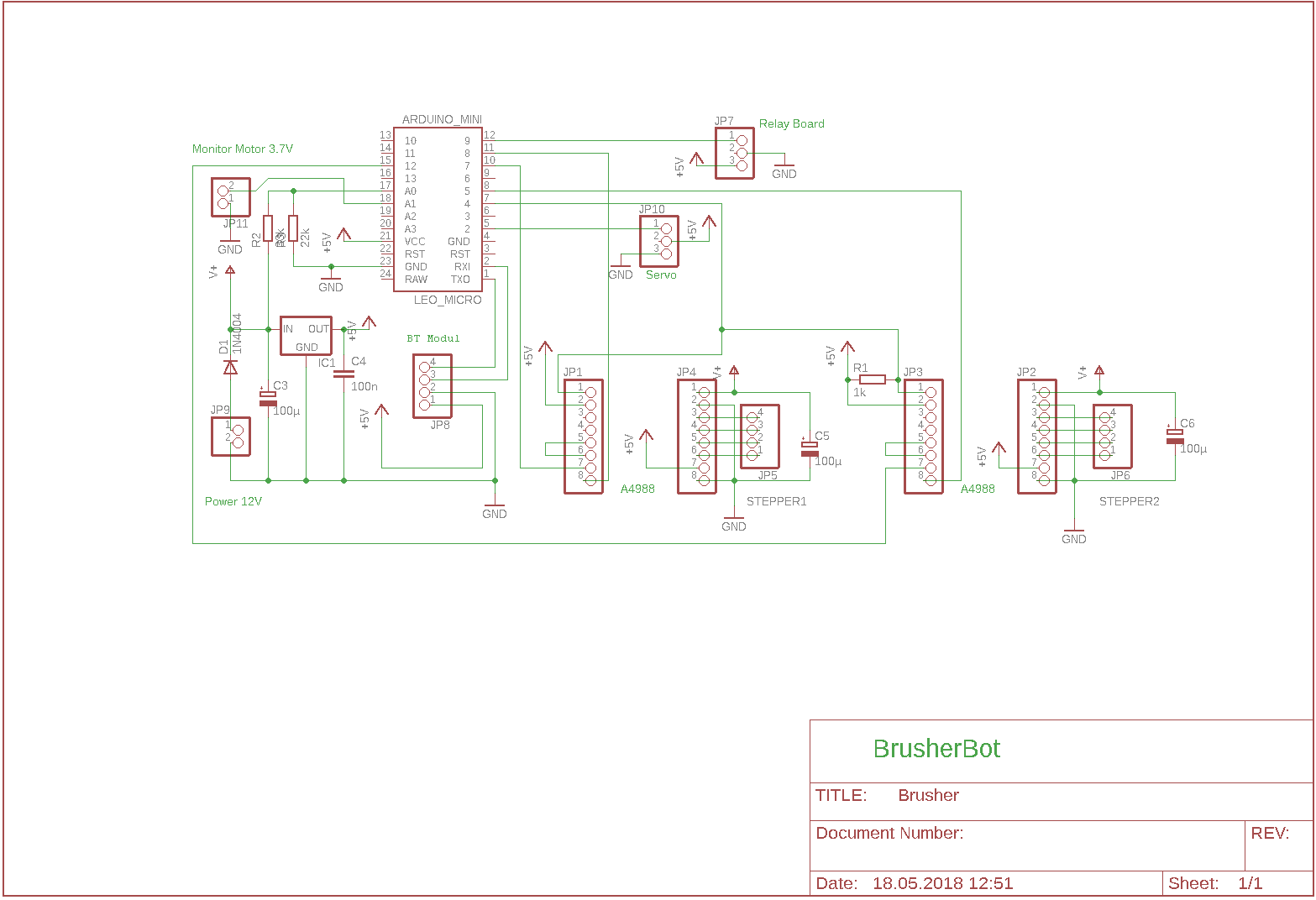
Electronic:The electronic part can be soldered to a breadboard. See the attached schematic for detail.
I also attaches the eagle sch-file if you like to make your own pcb.
To protect the electronic from moisture, everything including the batteries can be built into a pvc box.
The power supply is realized by two seperate LiPos for brush motor that needs high current and another one for the rest.
Use fuses for both circuits, LiPos can generate extreme high current !
To get the right current into your stepper motors it is very important to adjust the A4988 drivers.
Arduino:
For the control of the GRawler, I opted for the micro version of the Arduino Leonardo. This has a built-in USB controller and can thus easily program. The number of IO pins is sufficient for our purposes. For installing the IDE and choosing the right board use this guide.
After this you can download the attached sketch.
Changes to make in the Code:
The up/down values for the servo must be found experimentally and can be edit at top of the code:
#define ServoDown 40 // use Value 30-60#define ServoUp 50 // use Value 30-60
The code will NOT run on other Arduinos that don't use the ATmega32U4. These ones use different timers.
BT Control:
For remote controlling our little crawler I use a BT module and the App "Joystick BT commander". In order not to have to reinvent the wheel, there is also a guide.
And a guide for the BT module, use 115200bps baudrate. Pairing code is " 1234".
The App comes up with 6 buttons( we only need 3) and a joystick. Use preferences to configure the button labels,
1. Brush on/off
2. Motors on/off
3. Wiper up/down
Uncheck the box " return to center"
and check "auto connect"
I have attached some screen shots from my phone for details.
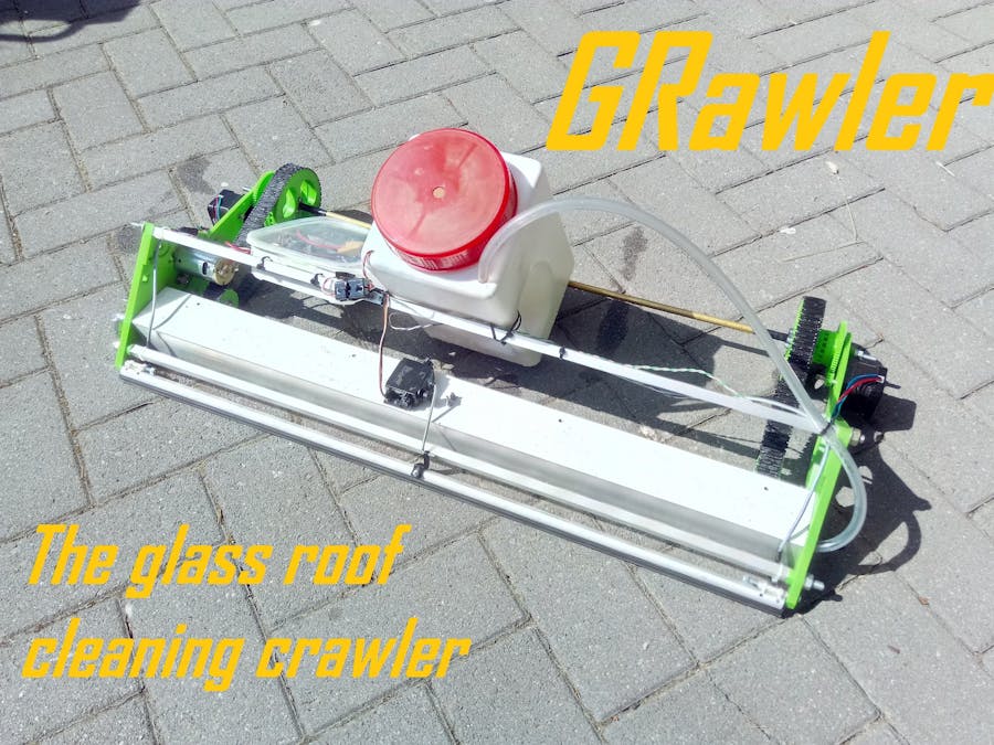
Now it is showtime for cleaning the roof.
- Put the GRawler on the roof
- Fill in some water (warm is better !)
Get a Clear View :-)

_PnKPri8a6q.jpg?auto=compress%2Cformat&w=48&h=48&fit=fill&bg=ffffff)


_3u05Tpwasz.png?auto=compress%2Cformat&w=40&h=40&fit=fillmax&bg=fff&dpr=2)
Comments