

Hardware components | ||||||
| × | 1 | ||||
 |
| × | 1 | |||
 |
| × | 5 | |||
| × | 1 | ||||
 |
| × | 3 | |||
Software apps and online services | ||||||
| ||||||
| ||||||
| ||||||
| ||||||
This project is a simple Human Response Timer built using the RT-Spark development board with an STM32F407ZGT6 microcontroller. It measures how quickly a person can react when an RGB LED turns on.
The program first waits for a random amount of time between one and three seconds. This prevents the user from guessing when the signal will appear. After the delay, the RGB LED lights up, telling the user to press the push button as fast as possible.
When the button is pressed, an external interrupt is triggered, allowing the microcontroller to immediately detect the user's response. The program then records the result and determines whether the reaction time is fast, average, or slow. A different RGB LED color is displayed to show the result.
To provide immediate feedback, the system categorizes the response speed using colored LEDs:
- Red LED = Fast reaction
- Green LED = Average reaction
- Blue LED = Slow reaction
This design also illustrates the efficiency of interrupt-driven I/O: the processor continues executing instructions (incrementing the counter) in the foreground while the interrupt fires the moment the button is pressed — no polling required.
HARDWARE DESIGNPhase 1: Circuit Description
Input — Push Button (SW1)
A tactile push button is connected between PC0 and GND. A 100 kΩ pull-up resistor holds the line HIGH when the button is released. Pressing the button pulls the line LOW, creating a falling edge that triggers the EXTI interrupt.
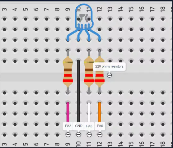
Output — RGB LED
A common-cathode RGB LED is connected to PA2, PA3, and PA0 through 220 Ω current-limiting resistors. The resistors protect the LED from excess current drawn from the GPIO output pins.
SOFTWARE DESIGNPhase 2: Project Setup
Create a new project in STM32CubeMX and search STM32F407ZGT6 in the MCU board selector and then choose the first one and name your project, and choose STMCubeIDE for Toolchain/IDE, then keep the default settings.
After that, generate code to save the project.
Phase 3: CubeMX Configuration
A new STM32 project was created targeting the STM32F407ZGT6. The following pin configurations were applied in STM32CubeMX:
Phase 4: Main Loop Logic
The main loop follows this sequence:
- All LEDs are turned OFF and the counter is cleared.
- A hardware RNG (HAL_RNG_GenerateRandomNumber) generates a random delay between 1, 000 and 3, 000 ms. This prevents the user from anticipating the signal.
- The randomly selected LED color is turned ON.
- A while (flag == 0) busy-wait loop increments the counter on every iteration.
- Once the ISR sets flag = 1, the loop exits and the counter value is saved.
- A feedback LED color is displayed based on the counter threshold.
- A 5-second display period follows before the next trial.
Phase 5: Interrupt Service Routine (ISR)
The external interrupt callback HAL_GPIO_EXTI_Callback is implemented as follows:
The flag variable is declared volatile to prevent compiler optimizations from caching the value in a register, ensuring the main loop detects the change immediately.
Reaction Time Classification
After the ISR fires, the counter value is classified into three categories:
Extra Credit — Averaging Ten Trials
A running sum and iteration counter are maintained across trials. After ten measurements, the average counter value is computed and stored in avgresponsetime. This reduces the effect of outlier responses.
iterations++;
sum = sum + counter;
if (iterations == 10) {
avgresponsetime = sum / 10;
iterations = 0;
sum = 0;
}
TESTINGPhase 6: Procedure
The breakpoint-based method described in the assignment was used: a breakpoint was placed immediately after the flag detection, and the counter variable was inspected in the STM32CubeIDE watch window.
Multiple trials were performed to observe consistency:
- The RNG produced a different delay on each trial, confirming no predictable pattern.
- The EXTI callback fired reliably on each button press with no missed interrupts observed.
- LED color changes correctly reflected the counter threshold logic.
The system successfully measured human reaction time across repeated trials. Representative counter values observed during testing are summarized below:
CONCLUSIONSNote on Oscilloscope / Logic Analyzer Verification
Verification of the LED activation and button press signals via logic analyzer or oscilloscope was not completed for this submission. Access to the required equipment was unavailable at the time of testing, and as a result, direct measurement of the reaction time interval in milliseconds could not be obtained through waveform capture. Reaction time was instead estimated indirectly through the loop counter method, with values examined via the STM32CubeIDE debugger watch window as described in Section 3.3 of the assignment. It is acknowledged that this represents a limitation of the current results, as oscilloscope verification would have provided a more precise and instrument-independent confirmation of the timing behavior. Should equipment access become available, capturing the rising edge on the LED output pin and the falling edge on PC0 simultaneously would allow the actual elapsed interval to be read directly from the time-division measurement.
Phase 7: General Reflections
This laboratory exercise provided a practical demonstration of interrupt-driven firmware design on an ARM Cortex-M microcontroller. The distinction between polling-based and interrupt-based event detection was reinforced: while a polling loop would have required the processor to continuously sample the pin state, the EXTI interrupt approach allows the processor to proceed with counter increments uninterrupted until the hardware-level event occurs, with no missed edges regardless of loop timing. This is a fundamental advantage of interrupt-driven architectures in real-time embedded systems.
The experiment also made concrete the relationship between human reaction time and processor throughput. The [VALUE] loop iterations accumulated per average trial demonstrate that an enormous number of operations — on the order of [VALUE] assembly instructions — can be completed by the processor within the time it takes a human to perceive a visual stimulus and physically respond to it. This illustrates why modern microcontrollers are capable of managing many concurrent tasks even within the span of a single human perceptual event.
Phase 8: Issues Encountered
- Several challenges arose during the development and testing process. Initial configuration of the EXTI peripheral in STM32CubeMX required careful selection of the falling-edge trigger mode, as the switch circuit uses an active-low configuration with a 100 kΩ pull-up resistor; an incorrect trigger selection (rising edge) produced no ISR execution during testing.
- A secondary concern was potential switch contact bounce. Because no hardware or software debouncing was implemented, rapid mechanical oscillation of the switch contacts could theoretically generate multiple EXTI triggers. In practice, the flag-based design mitigates this issue: once isr_flag is set to 1, subsequent ISR executions are harmless because the flag cannot be set to a value higher than 1, and the main loop exits the counting loop on the first detection. This provides an implicit debounce at the software level.


Comments