


Hardware components | ||||||
 |
| × | 1 | |||
 |
| × | 1 | |||
 |
| × | 1 | |||
 |
| × | 1 | |||
 |
| × | 1 | |||
 |
| × | 1 | |||
 |
| × | 1 | |||
 |
| × | 1 | |||
 |
| × | 1 | |||
 |
| × | 1 | |||
 |
| × | 1 | |||
 |
| × | 1 | |||
 |
| × | 1 | |||
Software apps and online services | ||||||
 |
| |||||
Hand tools and fabrication machines | ||||||
 |
| |||||
 |
| |||||
 |
| |||||
 |
| |||||
This section outlines the approach, tools, and processes used to develop the Smart Home Control System. The project integrates multiple engineering disciplines, including analog electronics, power electronics, embedded systems, and IoT, to create a robust and flexible smart home power management solution. The methodology covers the hardware design, software development, and system integration aspects required to bring this project to life.
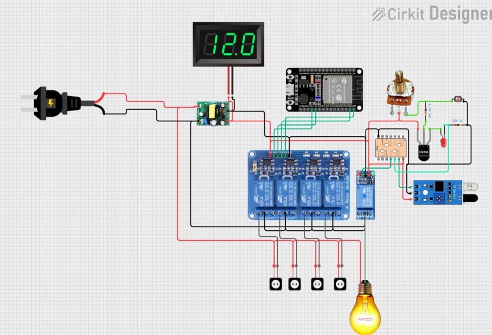
1. System Design and ArchitectureThe project was designed as a modular system with the following core components:
Power Supply Unit (PSU): Converts 220V AC to 5V DC using a rectifier and a switched-mode power supply (SMPS) circuit to power the ESP32 and other components.
- Power Supply Unit (PSU): Converts 220V AC to 5V DC using a rectifier and a switched-mode power supply (SMPS) circuit to power the ESP32 and other components.
Power Monitoring and Control: Utilizes a ZMPT101B voltage sensor and a current sensor to measure power consumption.
- Power Monitoring and Control: Utilizes a ZMPT101B voltage sensor and a current sensor to measure power consumption.
Automatic Lighting Control: Implements an LDR (Light Dependent Resistor) circuit in a voltage divider configuration connected to the base of an NPN transistor. This configuration allows the light to turn on or off based on ambient brightness levels, acting independently of the ESP32 and relying solely on analog electronic behavior.
- Automatic Lighting Control: Implements an LDR (Light Dependent Resistor) circuit in a voltage divider configuration connected to the base of an NPN transistor. This configuration allows the light to turn on or off based on ambient brightness levels, acting independently of the ESP32 and relying solely on analog electronic behavior.
Signal Generation: A 555 timer is configured in astable mode to generate continuous clock pulses, which can be used for timing or triggering purposes in the circuit. This timer operates as a standalone analog module, without any dependency on the microcontroller.
- Signal Generation: A 555 timer is configured in astable mode to generate continuous clock pulses, which can be used for timing or triggering purposes in the circuit. This timer operates as a standalone analog module, without any dependency on the microcontroller.
IoT Integration: The ESP32 microcontroller serves as the main control and communication unit, enabling Wi-Fi connectivity and real-time data transmission to the Blynk platform for remote monitoring and control.
- IoT Integration: The ESP32 microcontroller serves as the main control and communication unit, enabling Wi-Fi connectivity and real-time data transmission to the Blynk platform for remote monitoring and control.
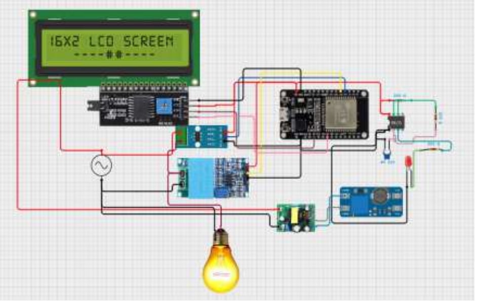
User Interface and Utilities: An LCD display is included to show system parameters locally, and a USB output is provided for mobile device charging. A potentiometer allows voltage tuning in the booster module, offering adjustable output for various devices.
- User Interface and Utilities: An LCD display is included to show system parameters locally, and a USB output is provided for mobile device charging. A potentiometer allows voltage tuning in the booster module, offering adjustable output for various devices.
Power Supply Design: A robust 220V AC to 5V DC converter was developed using a bridge rectifier, filter capacitor, and a switched-mode power supply (SMPS). This unit ensures efficient and safe voltage regulation to operate the ESP32, sensors, and additional modules.
- Power Supply Design: A robust 220V AC to 5V DC converter was developed using a bridge rectifier, filter capacitor, and a switched-mode power supply (SMPS). This unit ensures efficient and safe voltage regulation to operate the ESP32, sensors, and additional modules.
Sensor Integration: The ZMPT101B voltage sensor and a current sensor are connected to the analog input pins of the ESP32. These sensors provide real-time measurements of electrical parameters, which are processed and visualized remotely.
- Sensor Integration: The ZMPT101B voltage sensor and a current sensor are connected to the analog input pins of the ESP32. These sensors provide real-time measurements of electrical parameters, which are processed and visualized remotely.
Lighting Control: A standalone automatic lighting system was designed using an LDR in a voltage divider configuration with an NPN transistor. This circuit independently controls the lighting based on ambient brightness and operates purely through analog electronics, without relying on the ESP32.
- Lighting Control: A standalone automatic lighting system was designed using an LDR in a voltage divider configuration with an NPN transistor. This circuit independently controls the lighting based on ambient brightness and operates purely through analog electronics, without relying on the ESP32.
Clock Signal Generation: A 555 timer IC is configured in astable mode to provide a continuous clock pulse. This circuit functions autonomously and serves as a timing reference or trigger in the system.
- Clock Signal Generation: A 555 timer IC is configured in astable mode to provide a continuous clock pulse. This circuit functions autonomously and serves as a timing reference or trigger in the system.
Display and Output Features: An LCD display module is included for local visual feedback of system states. Additionally, a USB port provides convenient charging for mobile devices, drawing power from the main SMPS.
- Display and Output Features: An LCD display module is included for local visual feedback of system states. Additionally, a USB port provides convenient charging for mobile devices, drawing power from the main SMPS.
The software for the ESP32 was developed using the Arduino IDE, incorporating Wi-Fi setup, sensor data acquisition, and communication with the Blynk platform for seamless IoT integration. To ensure efficient and reliable data transfer, MQTT protocols were implemented, reducing latency and enhancing communication stability. The Blynk platform was configured for real-time data visualization, allowing users to monitor and control smart home components remotely through a mobile app, providing a user-friendly interface for managing the entire system.
4. System Integration and TestingIntegration Testing: All modules were tested individually, then assembled onto a unified board. Integration tests were conducted to ensure communication across all parts.
- Integration Testing: All modules were tested individually, then assembled onto a unified board. Integration tests were conducted to ensure communication across all parts.
Power Efficiency Testing: The power supply was tested for stable voltage output under different loads, ensuring safe operation of the ESP32 and sensors.
- Power Efficiency Testing: The power supply was tested for stable voltage output under different loads, ensuring safe operation of the ESP32 and sensors.
Subfunction Validation: Independent analog circuits like the LDR-based light controller and 555 timer module were verified for standalone operation, ensuring reliability without digital interference.
- Subfunction Validation: Independent analog circuits like the LDR-based light controller and 555 timer module were verified for standalone operation, ensuring reliability without digital interference.
Final Assembly: Components were organized and enclosed in a protective case, considering layout, airflow, and insulation for long-term stability and safety.
- Final Assembly: Components were organized and enclosed in a protective case, considering layout, airflow, and insulation for long-term stability and safety.
Field Testing: The system was deployed in a simulated home environment where power usage was monitored, lighting responded to changes in ambient light, and mobile control was tested successfully.
- Field Testing: The system was deployed in a simulated home environment where power usage was monitored, lighting responded to changes in ambient light, and mobile control was tested successfully.
User Feedback: Initial users confirmed ease of use, clarity of data visualization, and usefulness of added functions like USB charging and automatic lighting.
- User Feedback: Initial users confirmed ease of use, clarity of data visualization, and usefulness of added functions like USB charging and automatic lighting.
Power Noise Management: Filtering capacitors and regulated components minimized ripple and electromagnetic interference.
- Power Noise Management: Filtering capacitors and regulated components minimized ripple and electromagnetic interference.
Wi-Fi Stability: Auto-reconnect features were programmed into the ESP32 to maintain reliable cloud communication.
- Wi-Fi Stability: Auto-reconnect features were programmed into the ESP32 to maintain reliable cloud communication.
System Isolation: Analog subfunctions were designed to work independently to ensure robustness and minimize microcontroller dependency.
- System Isolation: Analog subfunctions were designed to work independently to ensure robustness and minimize microcontroller dependency.
Adding energy analytics using AI for predictive power management.
- Adding energy analytics using AI for predictive power management.
Integrating voice control or mobile notifications for enhanced user experience.
- Integrating voice control or mobile notifications for enhanced user experience.
Expanding the system to control more devices with advanced power measurement and automation.
- Expanding the system to control more devices with advanced power measurement and automation.


_3u05Tpwasz.png?auto=compress%2Cformat&w=40&h=40&fit=fillmax&bg=fff&dpr=2)

Comments