

This project describes how to build a battery optimized proof-of-concept with the Orange NB-IoT Rapid Development Kit. At the end of the tutorial you will have a NB-IoT temperature and humidity sensor device which runs for months on a battery. Visualise the data on a dashboard in Orange Maker IoT Cloud and forward it to your own application by subscribing to the MQTT broker.
How will the power consumption reduction be achieved?The Orange RDK is build around the Mbili Arduino compatible board together with a NB-IoT communication module or NB-IoT Bee. Both implement a sleep mode or power saving mode, which can be enabled by software or is triggered automatically when no activity is detected. In this example both of these modes will be used to lower the current consumption as a first step.
Every 5 minutes the temperature and humidity will be sampled and transmitted over NB-IoT to Orange Maker, battery status every hour. In between, the full setup is in deep sleep mode.
Step 1 Prepare the Mbili board to use the RTC external interruptThe external interrupt pin of the RTC can be connected to A7 of the microcontroller. By default this pin is used to measure the voltage of the solar panel. By cutting the connection of SJ13 and solder the connection on SJ18, the external interrupt pin SQW/INT of the DS3231 RTC is connected to A7.
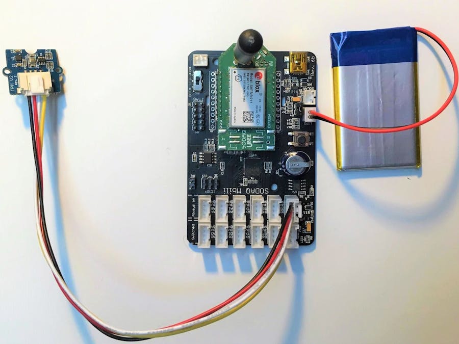
The TPHv2 sensor, included in the kit, has a Bosch BME280 sensor which can measure temperature, humidity and atmospheric pressure. It is designed to be low power and will consume some uA.
Connect the TPHv2 to the Grove connector with SCL/SDA of the I2C.
Connect the battery to the LiPo Battery connector.
Connect the USB cable to the Mbili and your PC.
Login to Orange Maker IoT Cloud.
Go to Playground or any other ground you have created and click on connect device.
From the device catalogue select the Orange NB-IoT RDK.
Select Orange as NB-IoT network provider
Give your device a name. Fill in the IMEI, which you can find on the uBlox Sara N211 module of the NB-IoT Bee. Click Connect to finish.
Once the device has been created in Orange Maker, all the assets or sensors and inputs that the kit contains are automatically generated, including temperature and humidity. The asset for the battery is missing and needs to be set manually.
Click on New Asset.
Name it battery (needs to have the same name as used in the example sketch).
Under Profile, choose Number as the type.
Click Create Asset.
Download the Orange NB-IoT RDK Low Power library attached to this project. Unzip the folder if needed and place it in the Arduino libraries folder under Documents >> Arduino >> Libraries.
(If you already have the standard AllThingsTalk arduino-nbiot-sdk-master, you will need to move this out of the Arduino Libraries folder to have no compilation errors)
In the Orange NB-IoT Kit Low Power SDK library folder, open the Keys.h file with an editor. This file contains the authentication keys to have access to your device in the Orange Maker IoT Cloud.
Go to the device created in Orange Maker. Click on Settings
Select Authentication
Copy paste the Device ID and Device Token into the keys.h file. Save and close the file.
#ifndef KEYS_h
#define KEYS_h
//DEVICE_TOKEN & DEVICE_TOKEN can be found in Orange Maker
//under Device >> Settings >> Authentication
const char* DEVICE_ID = "your Device ID";
const char* DEVICE_TOKEN = "maker:your Device Token";
//Orange SIM Card APN:
// - Orange NB-IoT RDK included SIM card => starter.att.iot
// - Maker SIM => att.iot
// - Light or Plus SIM => nbiot.iot
const char* APN = " starter.att.iot";
#endif
Connect the Mbili by USB to your computer. Open the Arduino IDE. Go to Tools >> Board >> select the SODAQ Mbili. If required also select the port.
Go to File >> Examples >>.Orange-NB-IoT-RDK-LowPower >> Orange-NB-IoT-RDK_TemperatureHumidity_Low-Power
Click Upload.
When the upload is done, you can disconnect the USB cable.
The current drawn from the battery can now be measured with a 1 ohm resistor on jumper JP4.
How to measure the battery current is explained in the Orange NB-IoT RDK power consumption measurement project.
During sleep mode the full setup will only consume between 200 and 300uA. While transmitting the payload, there will be the obvious peak currents, but are very limited in time. After transmission there is the Radio Resource Control that releases the NB-IoT module from the base station. Here in this example, the release assistance feature is used, for immediate release after transmission.
Step 6 Create a dashboardNow the device is sending data to the Orange Maker IoT Cloud. Time to make a dashboard!
Go to Orange Maker >> Devices and select the device you have created. Check if you have received data.
Click on Create Pinboard.
Select the assets to visualise and click Create Pinboard.
Basic controls will be generated. Click on the edit button at the right top corner.
Each control can be edited by selecting the settings icon in each control. Size, type of control, time scale can edited.
Example
To integrate this into your own application, you can subscribe to the MQTT broker.
How to do this is explained in Connecting a NB-IoT Device to an MQTT Client
The Mbili board has an ATmega1284P microcontroller that can be set by software into sleep mode. In this mode current consumption can be reduced to less than 300uA by disabling all peripherals while stalling the microcontroller core. Waking up from sleep mode can be done in 2 different ways, internal watchdog timer or external interrupt. The watchdog timer maximum interval is 8s. While with the external interrupt the controreller will be stalled until the external interrupt is triggerd, which can happen any time or on any event.
To wake up from sleep mode, the external interrupt of the DS3231 Real Time Clock will be used. This interrupt can be set to trigger every second, minute or hour and also on a specific time in a day.
On the Mbili board there is also an AT45DB161E SPI Dataflash, which is not used in this example, but has an ultra deep sleep mode of typically 400nA. As it is not used, during initialisation of the board, the dataflash will be set to this mode by the specific command. Otherwise it will consume typically 25uA in standby mode.
During active run time of the ATmega1284P MCU current consumption will be around 7mA. Setting all unused I/O pins to a digital output at initialisation, the current can be reduced with around 1mA.
To reduce the current consumption after sending data over NB-IoT to the Orange Maker IoT platform the Release Assistance feature of NB-IoT will be used to immediately enable the power saving mode (PSM) of the module. Normally after sending data, it will take up to 20s before the base station will set to the module to the inactive state and release the RRC (radio resource connection). This is done in the assumption that the module will receive downlink data as acknowledgement. In this example only UDP uplink data transfer is used, so the RRC can be released after sending each data packet. This will result in an immediate drop in power consumption. To achieve this, the +NSOSTF AT command with flag 0x200 will be used to transmit the UDP packet instead of the +NSOST command.


Comments