

Hardware components | ||||||
 |
| × | 1 | |||
| × | 1 | ||||
| × | 1 | ||||
 |
| × | 1 | |||
 |
| × | 1 | |||
 |
| × | 8 | |||
 |
| × | 2 | |||
 |
| × | 2 | |||
Software apps and online services | ||||||
 |
| |||||
| ||||||
I've converted several laptop keyboards to USB as documented in my Hackster and Instructable writeups but I've never tried the same methods on a desktop keyboard.
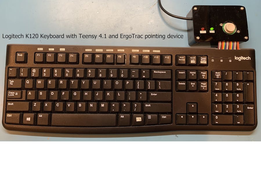
The Logitech K120 keyboard shown below was my guinea pig.
The row and column signals from the key switches are made with traces on plastic sheets that route to the controller in the upper right corner of the keyboard.
The end of the traces are pressed against the pads of a small circuit board with a "blob top" controller chip. I took measurements with a micrometer so I could match the mounting holes and trace locations with a new PCB.
The new OSH Park board shown below only has connections for the 26 signal traces and ground. It is made using the Eagle file “Logitech_K120.brd” or the zipped Gerber file "Logitech_K120_2021-12-31.zip" from my repo.
The traces on the plastic sheets extend over the pads on the PCB. The picture below shows the PCB traces could be adjusted slightly to the right but it's good enough to make a connection.
The signal connection is made by screwing down the metal bar that mashes the plastic traces against the PCB pads.
The 26 signal wires plus ground were soldered to the PCB and routed to a Teensy 4.1. Other, less powerful Teensy microcontrollers could be used but I wanted to try the 4.1. A Dremel tool was used to trim the plastic on the keyboard case so the wires could escape.
This shows the keyboard put back together.
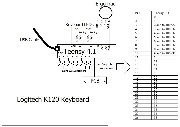
I ended up visually following the traces for the modifier keys to determine their pin connections because my standard matrix decoder code would only give results for the keys on the right side of the keyboard. This was caused by the high resistance traces on the plastic sheets and the 33 KΩ pullups inside the Teensy. For example, a pressed “X” key switch measured over 32 KΩ at the Teensy yet the keypad minus key (in the upper right corner) measured only 2 KΩ. The schematic below shows the resistor divider voltages for the "X" key. Changing to 100 KΩ external pullup resistors brought the voltage down so it is seen as a logic low.
The 100 KΩ pull up resistors are soldered to the Teensy inputs.
The matrix below gives the PCB pad number and Teensy I/O number for every key. The keypad keys start with KP.
Using this matrix, I wrote an Arduino USB keyboard routine based on the Teensyduino “Micro-Manager” functions. The keyboard code is called “Logitech_K120_4p1.ino” and it can be downloaded from my repo.
This keyboard has no Fn modifier key but it does have two Windows keys so I made the right side Windows key act as an Fn key. This allowed me to add media controls as follows:
Fn-F1 = Mute
Fn-F2 = Volume Down
Fn-F3 = Volume Up
I used a plastic project box to house the Teensy. The lid is cut from a sheet of acrylic and has holes for CAPS and NUM Lock LEDs. The USB cable enters the box thru a slit on the side.
The Teensy project box with LEDs is shown prior to adding the ErgoTrac pointing device.
The ErgoTrac pointing device, marked N320-4828-T001/20 is shown below. This one came from EBay, and is sold as FID-828-100/20. These pointers are used in certain Fujitsu Laptops and may have the FPC connector on the top or the bottom. I used four discreet wires instead of an FPC cable to hook up to the Teensy 4.1. I’ve also used a Teensy 3.2 with this device in a Fujitsu laptop as documented here. The pinout for the FPC is as follows:
FPC Pin 1 = 3.3 volt reference pulse
FPC Pin 2 = X direction
FPC Pin 3 = Y direction
FPC Pin 4 = Ground
After completing the keyboard scan, the Teensy 4.1 sends a logic high to pin 1 on the ErgoTrac which translates to a voltage on pins 2 and 3 that varies based on movement of the pointing head. These voltages are converted by the ADC in the Teensy and compared to the resting values. The ADC takes 8 readings and averages them to filter out noise. Once finished, the Teensy sends the reference on pin 1 low because this signal needs to be a pulse, not a constant level. The following table gives the X and Y pulse voltages at rest and pushed hard in each direction.
The Teensy code saves the X and Y values at startup as the "at rest" voltage, then it scans the keyboard and ErgoTrac about every 25mec. X or Y voltage readings that are not “at rest” values (with an added noise margin) are converted to relative mouse movement values and sent over USB.
This picture shows initial testing of the ErgoTrac with the Teensy 4.1.
The finished ErgoTrac inside the box with a hole in the lid.
This picture shows the finished keyboard with the ErgoTrac. I’ve added labels for special function keys. I never use Scroll Lock or Pause so these keys have been repurposed as left and right mouse buttons.
The ErgoTrac works well with the default values but the following Fn-function keys can fine tune the settings. The right Windows key acts as the Fn key.
Fn-F5 = Toggle ErgoTrac On/Off. Wakes up turned On. Left/right mouse buttons always function
Fn-F6 = Change Speed and Noise Zone back to the default values used at startup
Fn-F7 = Decrease cursor speed (takes several presses to notice a difference)
Fn-F8 = Increase cursor speed (takes several presses to notice a difference)
Fn-F9 = Decrease Noise Zone (too small and the cursor will move on its own due to noise)
Fn-F10 = Increase Noise Zone (too big and it will take excessive pressure to get any movement)
Fn-F11 = Recapture the ErgoTrac "at rest" X and Y values. Use this if temperature changes over time cause the cursor to start drifting.
The code has three cursor speeds based on how hard the ErgoTrac is pushed. Light pressure moves the cursor slowly for fine control. Medium and hard pressure causes medium and fast cursor movement. This comes in handy to move the cursor quickly across the screen.
The USB Composite keyboard and ErgoTrac code is called “Logitech_K120_4p1_ergotrac.ino”and it can be downloaded from my repo.
Note:
There is an older Logitech K120 keyboard (shown below) that has a different key matrix and connection method. It will not work with the above project.
Let me know if you have any questions


Comments