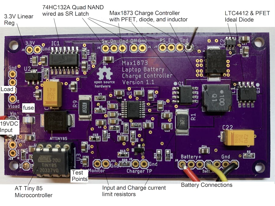
Frank Adams
Published © Apache-2.0

Laptop Battery Charge Controller

Max1873 and ATtiny85 are used to charge a laptop lithium battery pack.

AdvancedFull instructions providedOver 1 day4,709
Laptop Battery Charge Controller

Things used in this project

Hardware components

MAXIM INTEGRATED - MAX1873
R, S, or T part number for 2, 3, or 4 series wired lithium cells
×1
ATtiny85
Microchip ATtiny85
×1
Analog Devices LTC4412
×1
AP7381-33Y-13
Made by Diodes Incorporated
×1
onsemi MC74HC132ADG
×1
onsemi FDS4435BZ
×2
onsemi MMBF170
×1
B540C-13-F
Made by Diodes Incorporated
×2
0469005.WR
Made by Little Fuse
×1
NRS8030T100MJGJ
Made by Taiyo Yuden
×1
KEMET Electronics Corporation T495X686K025ATE200
×1
KEMET Electronics Corporation T495X476K035ATE200
×1
CC0805MRX5R6BB225
Made by Yageo
×2
UMK212BJ104KG-T
Made by Taiyo Yuden
×13
GMK212BJ224KGHT
Made by Taiyo Yuden
×2
08055C473KAT2A
Made by AVX
×2
KEMET Electronics Corporation C0805C102K5RACTU
×1
GMK212B7105KG-T
Made by Taiyo Yuden
×6
Panasonic ERA-3AEB104V
×3
RNCP0603FTD10K0
Made by Stackpole Electronics Inc
×3
RC0603JR-071KL
Made by Yageo
×3
RNCP0603FTD4R70
Made by Stackpole Electronics Inc
×2
Panasonic ERA-3AEB2491V
×1
Panasonic ERA-3AEB752V
×1
Panasonic ERA-3AEB4992V
×2
RC0603FR-0782KL
Made by Yageo
×1
RC0603FR-07160KL
Made by Yageo
×1
RT0603DRE0734K8L
Made by Yageo
×1
Vishay WSL2512R0330FEA
×1
Vishay WSL2512R2000FEA
×1
110-43-308-41-001000
Made by Mill-Max Manufacturing Corp.
×1
OSH Park Charge_Controller
Use Eagle board file Charge_Controller.brd This board is also available on OSH Park as a shared project titled Charge_Controller
×1

Software apps and online services

Arduino IDE
Arduino IDE
Add the AT Tiny library
Autodesk Eagle

Hand tools and fabrication machines

SparkFun Tiny AVR Programmer

Story

Read more

Schematics

Charge_Controller.sch

Schematic of Max1873 Battery Charger

Charge_Controller.brd

Layout of Max1873 Battery Charger

Code

Max1873_Supervisor_3series.ino

C/C++
Arduino code for ATtiny85 controlling Max1873 with 3 series battery.
/* Copyright 2021 Frank Adams
   Licensed under the Apache License, Version 2.0 (the "License");
   you may not use this file except in compliance with the License.
   You may obtain a copy of the License at
       http://www.apache.org/licenses/LICENSE-2.0
   Unless required by applicable law or agreed to in writing, software
   distributed under the License is distributed on an "AS IS" BASIS,
   WITHOUT WARRANTIES OR CONDITIONS OF ANY KIND, either express or implied.
   See the License for the specific language governing permissions and
   limitations under the License.
*/
// This ATTiny85 program controls the enable pin on the Max1873 so it will safely charge the Li+ laptop battery in a 3 series pack.
// Assumptions: 
//    a. Maximum battery charge current is set at 1 amp.
//    b. Battery Pack has 3 series cells, each cell fully charged at 4.2 volts, giving a pack voltage of 12.6 volts.
//    c. NTC Thermistor resistance in ohms is 13.6K @ 18C, 9.3K @ 27C, 5.3K @ 41C, 3.2K @ 59C
//    d. Charge current, battery voltage, and Temperature inputs to the ATTiny use the resistor divider values on the schematic. 
// Program Features:
// 1. The ATTiny keeps track of how long charging has been going on and shuts down the Max1873 after a defined maximum time. 
// 2. The Pi uses a GPIO pin to send a 3.3 volt logic signal to the ATTiny to turn off charging. 
//    This should be done if the Pi detects (over the SM Bus) that the battery temperature or voltage has gone too high.
// 3. The ATTiny ADC reads the battery temperature sensor (10K NTC thermistor) at startup and then while charging to see 
//    if the temperature rises too much and the Max1873 needs to stop charging. 
// 4. The ATTiny ADC reads the battery voltage prior to enabling the charger to see if the battery is ready for a normal charge. 
//    If the voltage is too low, the routine will pulse the charger enable signal to slowly bring the battery voltage up. 
//    The pulse duration will increase as the battery voltage rises.
// 5. The ATTiny ADC reads the charge current from the Iout pin of the Max1873 to see when it has reached trickle
//    charge levels and then shuts down charging. 
//
// Some Dell batteries will need SMBus communication from the Pi before they will accept charge current. 
// If the ATTiny reads a charge current at or near zero, (meaning the battery is not accepting a charge), 
// the Max1873 is kept enabled so that when the Pi sends the appropriate commands over the SM Bus, the battery will begin charging.
//   
// The ATTiny is powered from the low voltage (5.4V) regulator in the Max1873 which only operates when the 19.5VDC wall supply is  
// plugged in. This Max1873 regulator can only source 3ma and it meaasures 2.5ma when the ATTiny is running at 1MHz.  
// Any higher clock frequency will overload the regulator. It will also overload the regulator if the analog input voltages
// are between 1.5 and 2.5 volts. To avoid this, the internal 1.1 volt ADC reference is used and all analog input 
// voltages are scaled down to 1.1 volts max. 

// Release History
// July 1, 2020  Original Release

// ATTiny Logic Pins
#define pi_turnoff 0 // Pin 5 PB0 is an input. 1=turnoff. PCB has external pull down resistor
#define max_en 1 // Pin 6 PB1 drives BS170 NFET that turns Max1873 on and off. 0=On, 1=Off
// ATTiny Analog Pins
#define Vbat A1 // Pin 7 ADC1 receives divided down battery pack voltage
#define bat_temp A2 // Pin 3 ADC2 receives divided down battery temperature voltage
#define iout A3 // Pin 2 ADC3 receives divided down Max1873 Iout voltage
// Battery charging values
#define precharge 492 // this is a battery voltage of 9 volts. Pulse charge until voltage is above this level.
#define trickle 233 // Trickle charge trip level that turns off the charger. 233=250ma charge current
#define no_charge 11 // Near zero "no-charge" level equates to 12ma
#define temp_limit 150 // 150 is roughly a 10 degree temperature increase
#define max_minutes 300 // maximum charging time in minutes

// Globals
int pulse_on = 100; // "On" time in msec for precharge. This is adjusted based on the battery voltage
int pulse_off = 1900; // "Off" time in msec for precharge. This is adjusted to give a total cycle time of 2 seconds
int charge_level; // holds ADC average value from Iout pin of Max1873.  
int old_charge_level = 750; // holds ADC value from the previous loop
int temperature; // holds adc average value from 10K NTC battery temperature thermistor 
int temperature_start; // holds adc average value from battery temperature thermistor at power up
int battery_voltage; // holds adc average value of battery pack voltage 
int minute_count = 0; // Minute counter
int loop_count = 0; // Loop counter

// Function reads the selected ADC channel multiple times with the specified wait time between reads
int read_adc(int wait, int adc_chan) 
{ 
  int val_1 = analogRead(adc_chan); // first read after selecting the ADC channel is suspect so throw it away
  delay(wait); // wait before reading again
  val_1 = analogRead(adc_chan); // save this as the more accurate first read
  delay(wait); // wait before reading again
  int val_2 = analogRead(adc_chan);  // second read
  delay(wait); // wait before reading again
  int val_3 = analogRead(adc_chan);  // third read
  delay(wait); // wait before reading again
  int val_4 = analogRead(adc_chan);  // fourth read
  return ((val_1 + val_2 + val_3 + val_4)/4); // return average ranging from 0 to 1023 for 0 to 1.1 volts.   
}

void setup()
{
  analogReference(INTERNAL1V1); // use the 1.1 volt reference in the ATTiny for the ADC  
  pinMode(Vbat, INPUT); // divided down battery voltage is input to the ADC on this pin
  pinMode(bat_temp, INPUT); // voltage divider with NTC thermister is input to the ADC on this pin
  pinMode(iout, INPUT); // divided down voltage from the Max1873 Iout signal is input to the ADC on this pin
  pinMode(pi_turnoff, INPUT); // Pi drives this logic input to 3.3V to turn off the Max1873. Pull down resistor on PCB
  pinMode(max_en, OUTPUT); // charge control output signal drives gate of BS170 NFET. NFET turned on will disable Max1873
  digitalWrite(max_en, HIGH); // keep charger off initially
  delay(2000); // wait to let the battery temperature and voltage stabilize
// Save initial battery temperature
  temperature_start = read_adc(100,bat_temp); // Save the starting battery temperature
// Check battery voltage 
  battery_voltage = read_adc(100,Vbat); // Read the battery voltage
// Pulse charge if battery voltage is too low. 
  while(battery_voltage < precharge) { // stay in while loop if battery voltage is less than the defined precharge level
    // Do a pulse current pre-charge for 1 minute
    for (int i=0;i<30;i++) { // 2 second loop, 30 loops = 1 minute
      digitalWrite(max_en, LOW); // turn on charger
      delay(pulse_on); // This is the "On" pulse duration
      digitalWrite(max_en, HIGH); // turn off charger
      delay(pulse_off); // This is the "Off" pulse duration
    }
    delay(2000); // Wait before reading the battery voltage
    battery_voltage = read_adc(100,Vbat); // Read the battery voltage
    if (battery_voltage < 100) { // check if battery voltage is under 2 volts
      pulse_on = 100; // don't go below 100ms pulse time
    }
    else {
      pulse_on = battery_voltage; // ADC value makes good msec translation
    }
    pulse_off = 2000 - battery_voltage; // 2 second total cycle time
    // Check temperature
    temperature = read_adc(500,bat_temp); // Save the battery temperature
    // pulse charging should not cause a large temperature increase so stop charging and hang if the temperature limit is exceeded.
    if ((temperature_start - temperature) > temp_limit) {
      while(1) { // infinite loop to stop program. 
        digitalWrite(max_en, HIGH); // keep charger off
      }
    }
    // repeat the while loop with new battery voltage and pulse times
  }
// Proceed with main loop when battery voltage is above pre-charge levels  
}
   
void loop() // This loop repeats every 5 seconds if the Pi enables charging
{
  if (digitalRead(pi_turnoff)) {  // check if Pi wants the charger shut down
    digitalWrite(max_en, HIGH); // disable the Max 1873 charger
  }
  else {
// Check temperature
    temperature = read_adc(500,bat_temp); // Measure the battery temperature (takes 2 seconds)
    while((temperature_start - temperature) > temp_limit) {  // temperature increase beyond limit
      digitalWrite(max_en, HIGH); // turn charger off and stay in while loop until the battery cools down
      delay(10000); // wait before reading again
      temperature = read_adc(500,bat_temp); // Save the battery temperature 
    }
    digitalWrite(max_en, LOW); // Pi wants the charger enabled 
    delay(1000); // wait 1 second before measuring current
// Check charge current
    charge_level = read_adc(500,iout); // Save the charge level (takes 2 seconds)
// Charge current greater than the trickle charge trip level keeps the Max1873 enabled.  
// No charge current also keeps the Max1873 enabled while waiting for Pi to send turn on sequence over SM Bus. 
    if ((charge_level < trickle) && (charge_level > no_charge)) { // is current in the shutdown window? 
      if ((old_charge_level < trickle) && (old_charge_level > no_charge)) { // check levels from the last loop
        digitalWrite(max_en, HIGH); // drive charge control to "off" state
        while(1) { // infinite loop to stop program. 
        // The charge current has reached the turn off level 
        }
      }
    } 
    old_charge_level = charge_level; // save ADC value for next loop
// Keep track of total charging time
    loop_count++; // increment the loop counter
    if (loop_count >= 12) { // 12 loops at 5 seconds per loop
      loop_count = 0; // reset the loop counter
      minute_count++; // increment the minute counter
    }
    if (minute_count >= max_minutes) { // has charging reached the time limit?
      digitalWrite(max_en, HIGH); // turn charger off to be safe
      while(1) { // Battery charging has gone on for too long
        // infinite loop to stop program.
      }
    }
  }  
}

Max1873_Supervisor_4series.ino

C/C++
Arduino code for ATtiny85 controlling Max1873 with 4 series battery.
/* Copyright 2021 Frank Adams
   Licensed under the Apache License, Version 2.0 (the "License");
   you may not use this file except in compliance with the License.
   You may obtain a copy of the License at
       http://www.apache.org/licenses/LICENSE-2.0
   Unless required by applicable law or agreed to in writing, software
   distributed under the License is distributed on an "AS IS" BASIS,
   WITHOUT WARRANTIES OR CONDITIONS OF ANY KIND, either express or implied.
   See the License for the specific language governing permissions and
   limitations under the License.
*/
// This ATTiny85 program controls the enable pin on the Max1873 so it will safely charge the Li+ laptop battery in a 4 series pack.
// Assumptions: 
//    a. Maximum battery charge current is set at 1 amp.
//    b. Battery Pack has 4 series cells, each cell fully charged at 4.2 volts, giving a pack voltage of 16.8 volts.
//    c. NTC Thermistor resistance in ohms is 13.6K @ 18C, 9.3K @ 27C, 5.3K @ 41C, 3.2K @ 59C
//    d. Charge current, battery voltage, and Temperature inputs to the ATTiny use the resistor divider values on the schematic. 
// Program Features:
// 1. The ATTiny keeps track of how long charging has been going on and shuts down the Max1873 after a defined maximum time. 
// 2. The Pi uses a GPIO pin to send a 3.3 volt logic signal to the ATTiny to turn off charging. 
//    This should be done if the Pi detects (over the SM Bus) that the battery temperature or voltage has gone too high.
// 3. The ATTiny ADC reads the battery temperature sensor (10K NTC thermistor) at startup and then while charging to see 
//    if the temperature rises too much and the Max1873 needs to stop charging. 
// 4. The ATTiny ADC reads the battery voltage prior to enabling the charger to see if the battery is ready for a normal charge. 
//    If the voltage is too low, the routine will pulse the charger enable signal to slowly bring the battery voltage up. 
//    The pulse duration will increase as the battery voltage rises.
// 5. The ATTiny ADC reads the charge current from the Iout pin of the Max1873 to see when it has reached trickle
//    charge levels and then shuts down charging. 
//
// Some Dell batteries will need SMBus communication from the Pi before they will accept charge current. 
// If the ATTiny reads a charge current at or near zero, (meaning the battery is not accepting a charge), 
// the Max1873 is kept enabled so that when the Pi sends the appropriate commands over the SM Bus, the battery will begin charging.
//   
// The ATTiny is powered from the low voltage (5.4V) regulator in the Max1873 which only operates when the 19.5VDC wall supply is  
// plugged in. This Max1873 regulator can only source 3ma and it meaasures 2.5ma when the ATTiny is running at 1MHz.  
// Any higher clock frequency will overload the regulator. It will also overload the regulator if the analog input voltages
// are between 1.5 and 2.5 volts. To avoid this, the internal 1.1 volt ADC reference is used and all analog input 
// voltages are scaled down to 1.1 volts max. 

// Release History
// Dec 17, 2020  Original Release

// ATTiny Logic Pins
#define pi_turnoff 0 // Pin 5 PB0 is an input. 1=turnoff. PCB has external pull down resistor
#define max_en 1 // Pin 6 PB1 drives BS170 NFET that turns Max1873 on and off. 0=On, 1=Off
// ATTiny Analog Pins
#define Vbat A1 // Pin 7 ADC1 receives divided down battery pack voltage
#define bat_temp A2 // Pin 3 ADC2 receives divided down battery temperature voltage
#define iout A3 // Pin 2 ADC3 receives divided down Max1873 Iout voltage
// Battery charging values
#define precharge 673 // this is a battery voltage of 12.3 volts. Pulse charge until voltage is above this level.
//#define trickle 233 // Trickle charge trip level that turns off the charger. 233=250ma charge current
#define trickle 65 // Trickle charge trip level that turns off the charger. 65=70ma charge current
#define no_charge 11 // Near zero "no-charge" level equates to 12ma
#define temp_limit 150 // 150 is roughly a 10 degree temperature increase
#define max_minutes 300 // maximum charging time in minutes

// Globals
int pulse_on = 100; // "On" time in msec for precharge. This is adjusted based on the battery voltage
int pulse_off = 1900; // "Off" time in msec for precharge. This is adjusted to give a total cycle time of 2 seconds
int charge_level; // holds ADC average value from Iout pin of Max1873.  
int old_charge_level = 750; // holds ADC value from the previous loop
int temperature; // holds adc average value from 10K NTC battery temperature thermistor 
int temperature_start; // holds adc average value from battery temperature thermistor at power up
int battery_voltage; // holds adc average value of battery pack voltage 
int minute_count = 0; // Minute counter
int loop_count = 0; // Loop counter

// Function reads the selected ADC channel multiple times with the specified wait time between reads
int read_adc(int wait, int adc_chan) 
{ 
  int val_1 = analogRead(adc_chan); // first read after selecting the ADC channel is suspect so throw it away
  delay(wait); // wait before reading again
  val_1 = analogRead(adc_chan); // save this as the more accurate first read
  delay(wait); // wait before reading again
  int val_2 = analogRead(adc_chan);  // second read
  delay(wait); // wait before reading again
  int val_3 = analogRead(adc_chan);  // third read
  delay(wait); // wait before reading again
  int val_4 = analogRead(adc_chan);  // fourth read
  return ((val_1 + val_2 + val_3 + val_4)/4); // return average ranging from 0 to 1023 for 0 to 1.1 volts.   
}

void setup()
{
  analogReference(INTERNAL1V1); // use the 1.1 volt reference in the ATTiny for the ADC  
  pinMode(Vbat, INPUT); // divided down battery voltage is input to the ADC on this pin
  pinMode(bat_temp, INPUT); // voltage divider with NTC thermister is input to the ADC on this pin
  pinMode(iout, INPUT); // divided down voltage from the Max1873 Iout signal is input to the ADC on this pin
  pinMode(pi_turnoff, INPUT); // Pi drives this logic input to 3.3V to turn off the Max1873. Pull down resistor on PCB
  pinMode(max_en, OUTPUT); // charge control output signal drives gate of BS170 NFET. NFET turned on will disable Max1873
  digitalWrite(max_en, HIGH); // keep charger off initially
  delay(2000); // wait to let the battery temperature and voltage stabilize
// Save initial battery temperature
  temperature_start = read_adc(100,bat_temp); // Save the starting battery temperature
// Check battery voltage 
  battery_voltage = read_adc(100,Vbat); // Read the battery voltage
// Pulse charge if battery voltage is too low. 
  while(battery_voltage < precharge) { // stay in while loop if battery voltage is less than the defined precharge level
    // Do a pulse current pre-charge for 1 minute
    for (int i=0;i<30;i++) { // 2 second loop, 30 loops = 1 minute
      digitalWrite(max_en, LOW); // turn on charger
      delay(pulse_on); // This is the "On" pulse duration
      digitalWrite(max_en, HIGH); // turn off charger
      delay(pulse_off); // This is the "Off" pulse duration
    }
    delay(2000); // Wait before reading the battery voltage
    battery_voltage = read_adc(100,Vbat); // Read the battery voltage
    if (battery_voltage < 100) { // check if battery voltage is under 2 volts
      pulse_on = 100; // don't go below 100ms pulse time
    }
    else {
      pulse_on = battery_voltage; // ADC value makes good msec translation
    }
    pulse_off = 2000 - battery_voltage; // 2 second total cycle time
    // Check temperature
    temperature = read_adc(500,bat_temp); // Save the battery temperature
    // pulse charging should not cause a large temperature increase so stop charging and hang if the temperature limit is exceeded.
    if ((temperature_start - temperature) > temp_limit) {
      while(1) { // infinite loop to stop program. 
        digitalWrite(max_en, HIGH); // keep charger off
      }
    }
    // repeat the while loop with new battery voltage and pulse times
  }
// Proceed with main loop when battery voltage is above pre-charge levels  
}
   
void loop() // This loop repeats every 5 seconds if the Pi enables charging
{
  if (digitalRead(pi_turnoff)) {  // check if Pi wants the charger shut down
    digitalWrite(max_en, HIGH); // disable the Max 1873 charger
  }
  else {
// Check temperature
    temperature = read_adc(500,bat_temp); // Measure the battery temperature (takes 2 seconds)
    while((temperature_start - temperature) > temp_limit) {  // temperature increase beyond limit
      digitalWrite(max_en, HIGH); // turn charger off and stay in while loop until the battery cools down
      delay(10000); // wait before reading again
      temperature = read_adc(500,bat_temp); // Save the battery temperature 
    }
    digitalWrite(max_en, LOW); // Pi wants the charger enabled 
    delay(1000); // wait 1 second before measuring current
// Check charge current
    charge_level = read_adc(500,iout); // Save the charge level (takes 2 seconds)
// Charge current greater than the trickle charge trip level keeps the Max1873 enabled.  
// No charge current also keeps the Max1873 enabled while waiting for Pi to send turn on sequence over SM Bus. 
    if ((charge_level < trickle) && (charge_level > no_charge)) { // is current in the shutdown window? 
      if ((old_charge_level < trickle) && (old_charge_level > no_charge)) { // check levels from the last loop
        digitalWrite(max_en, HIGH); // drive charge control to "off" state
        while(1) { // infinite loop to stop program. 
        // The charge current has reached the turn off level 
        }
      }
    } 
    old_charge_level = charge_level; // save ADC value for next loop
// Keep track of total charging time
    loop_count++; // increment the loop counter
    if (loop_count >= 12) { // 12 loops at 5 seconds per loop
      loop_count = 0; // reset the loop counter
      minute_count++; // increment the minute counter
    }
    if (minute_count >= max_minutes) { // has charging reached the time limit?
      digitalWrite(max_en, HIGH); // turn charger off to be safe
      while(1) { // Battery charging has gone on for too long
        // infinite loop to stop program.
      }
    }
  }  
}

Laptop -Battery-Charger

Code and Circuit Board Information

Credits

Frank Adams

Frank Adams

4 projects • 11 followers
I am a retired Boeing engineer that enjoys experimenting with Pi, Arduino, and Teensy projects.

Comments