


The functionality of detecting objects by means of reflection has several applications, mainly in the area of automation, such as remote control commands.
From the automation aided by a sensor that can detect the presence of objects, it is possible to develop systems by means of digital printing, automatic activation of lamps, systems that can assign different functions based on the way different surfaces reflect the light that a reached.
Thus, one of these applications is present in the detection of objects, such as in a didactic safe using the TCRT5000 sensor and an LCD display, as shown in Figure 1 below.
For the development of this didactic case of the safe, you will learn both to assemble the basic circuit using the Arduino as in previous projects and to program.
The implemented didactic safe has a simple structure, containing the LCD (Liquid Crystal Display) display, the TCRT5000 reflective object sensor, and a push-button.
As the coin is inserted into the safe through the specific hole, the sensor detects its presence and already counts the total amount of coins, using the internal conditions in the developed program.
The detection of coins is made by the reflective sensor TCRT5000, which uses the LED to emit light and the phototransistor is activated when the light is reflected, thus performing a count.
In this article, you will learn how to program and use the TCRT5000 reflective sensor, as well as to know its physical structure, as this sensor uses reflection as a working principle.
Therefore, through this article you will learn:
- Know the structure of the TCRT5000 Reflective Optical Sensor with Transistor Output;
- Understand the operation of the TCRT5000 Reflective Optical Sensor with Transistor Output;
- Perform Communication between the TCRT5000 Reflective Optical Sensor with Transistor Output and the Arduino UNO R3;
- Present the structure of the TCRT5000 Reflective Optical Sensor with Transistor Output to the teaching case developed by SILICIOS LAB.
- Consctruct your PCBGOGO Printed Circuit Board for the Safe box for money.
Now, we will start the complete presentation of the development of the Didactic Safe Using LCD and the TCRT5000 Reflective Sensor.
Project Development MethodologyThis project consists of presenting a didactic model of a safe using the TCRT5000 reflective optical sensor with the Arduino UNO development board.
The project consists of the optical sensor, responsible for detecting the presence of objects through the emission of infrared light and the activation of the phototransistor when the light reflected by the object is detected.
The Arduino UNO development board will be responsible for receiving the logic level sent by the sensor and supplying the power so that the sensor can work, and finally, processing the signals received by the sensor. This is shown in Figure 2.
The signal emitted by the infrared light LED of the reflective sensor is emitted, and in this way, the light detects the coin, and soon after, the light is reflected in several directions, and a part is captured by the phototransistor of the reflective sensor as shown in Figure 3.
The TCRT5000 Reflective Sensor is basically constituted by an infrared light-emitting LED, the phototransistor responsible for making the switching of the light is detected and the structure used to couple the two devices mentioned.
Figure 4 illustrates the TCRT5000 reflective sensor.
The infrared LED emits light in several directions, and when that light hits the surface of the coin, it reflects the light and the phototransistor captures that light.
In this way, the sensor sends a low logic level to the digital pin of the Arduino and, on the other hand, while the sensor does not detect any object, it sends a high logic level.
All communication of the didactic safe will be done through the LCD display, which will send indicative messages to the user.
The Push Button will be used to send a low logic level to the digital pin 7 of the Arduino, so that the zeroing of the coin counter, implemented in the program, is done.
For this, a 10 kΩ pull-up resistor will be used to ensure that the pin has a high logic level, making it reach the low logic level when the Push Button is activated, thus avoiding an overflow.
To set up the experiment, first, make sure that your Arduino is turned off by disconnecting it from the USB cable.
Now, take the components and connect everything as shown in figure 5 below.
According to the wiring diagram shown in Figure 5, the experiment consists of the reflective sensor circuit, the Arduino UNO circuit, the Push Button circuit and the LCD display circuit.
The TCRT5000 sensor has 4 pins (two pins for the LED and two for the phototransistor), with two power pins (Vdc), the power pin of the phototransistor being connected to a 10kΩ resistor that will be connected to the 5 volts of the Arduino Uno by means of the protoboard and it will also be connected to the digital pin 6 of the Arduino to send the signal, and the pin also supplying the LED will be connected to a 220 Ω resistor that will be connected to the 5 Volts bus of the protoboard.
The remaining two pins, both the LED and the phototransistor will be connected to the reference bus of the protoboard, which will be connected to the GND pin of the arduino.
The Arduino uno will be responsible for processing the signal of the circuit as a whole and providing the power and reference. The push button used will be connected to the reference and to the pull-up resistor, to ensure high logic level on digital pin 6 of the arduino as long as the push button is not pressed.
The LCD display circuit will be the standard using the 4-bit connection (D4, D5, D6 and D7), together with the 10 kΩ potentiometer responsible for the contrast, and a 330 Ω resistor connected to the anode pin.
All the programming logic of the didactic safe was developed as commented on the following program:
/*
Conexões do display LCD ao arduino uno:
* LCD RS pino para o digital pino 12
* LCD Enable pin para o digital pino 11
* LCD D4 pino para o digital pino 5
* LCD D5 pino para o digital pino 4
* LCD D6 pino para o digital pino 3
* LCD D7 pino para o digital pino 2
* LCD R/W pino para o ground
* LCD VSS pino para o ground
* LCD VDD pino para o 5V
* LCD V0 pino para o potenciômetro
*/
#include <LiquidCrystal.h>//importando a biblioteca das funçoes do LCD
//pinos de interface da biblioteca
LiquidCrystal lcd(12, 11, 5, 4, 3, 2);
//********************INICIO-SENSOR TCRT5000***********************
int Objeto = 0;//variável utilizada para as informações do sensor
int Sensor = 6;// o pino de dados do sensor será conectado ao pino digital 6 do arduino
int moedas = 0;//variavel responsavel por contar as moedas
int botao_zerar_contagem = 7;//variavel responsável pelo botao que ira reiniciar a contagem das moedas.
int estado_botao;//variável utilizada para verificar o estada do botão.
//********************FIM-SENSOR TCRT5000***********************
void setup() { //função responsável por definir os pinos de entrada e saida do arduino
//********************INICIO-SENSOR TCRT5000***********************
pinMode(Sensor,INPUT);//define o pino Sensor como entrada de dados
pinMode(botao_zerar_contagem,INPUT);//define o pino do botao como entrada de dados
//********************FIM-SENSOR TCRT5000***********************
// Número de linhas e colunas do LCD utilizado
lcd.begin(16, 2);
// Função responsável por retornar a mensagem no LCD
lcd.setCursor(2,0);//setando o cursor do LCD na coluna 2 linha 0
lcd.print("SILICIOS LAB");//mensagem enviada para o LCD
lcd.setCursor(2,1);//setando o cursor do LCD na coluna 2 linha 1
lcd.print("Cofre 1 real");//mensagem enviada para o LCD
delay(4000);//aguarda 4 segundos para iniciar
lcd.clear();//apaga os caracteres no LCD
}
void loop() {
estado_botao = digitalRead(botao_zerar_contagem);//lendo o estado do botão.
if(estado_botao==LOW)//se o estada do botão for LOW, a contagem será reiniciada
{
lcd.setCursor(0,0);//desloca o cursor para a posição específica do texto da contagem
lcd.clear();//limpa a contagem anterior
moedas=0;//zera a contagem das moedas e reinicia a contagem.
}
else//se o estado do botão for contrário a LOW, ou seja, HIGH, o programa ira continuar o seu fluxo normalmente
{
}
Objeto = digitalRead(Sensor);//analise o sinal enviado pelo pino de dados do sensor
if(Objeto==0)//caso o sinal do sensor seja nível lógico 0, o sensor terá detectado um objeto
{
Serial.println("Moeda Recebida");//mensagem no monitor Serial
// inicia o curso do LCD na coluna 0, linha 1
lcd.clear();//apaga os caracteres no LCD
lcd.setCursor(0, 1);//setando o cursor do LCD na coluna 0 linha 1
// print the number of seconds since reset:
lcd.print("Moeda Recebida");
moedas=moedas+1;//a cada passagem por esta linha, o contador é incrementado com o valor 1.
lcd.setCursor(0, 0);// inicia o curso do LCD na coluna 0, linha 0
// print the number of seconds since reset:
lcd.print("Moedas = ");//mensagem enviada para o LCD
lcd.print(moedas);//mostra o valor da variável "moedas" no LCD
int aux=Objeto;//variável utilizada para armazenar a leitura atual do sensor
while(aux==LOW){//loop responsável por impedir o sensor de conte mais de uma vez a moeda enquanto ela está sendo colocada no cofre.
moedas=moedas;//enquanto o loop durar, o valor da variável será o mesmo.
lcd.setCursor(0,0);
lcd.print("Moedas = ");
lcd.print(moedas);
aux=digitalRead(Sensor);
}
}
else //caso o valor seja nível lógico 1, o sensor não estará detectando a presença de nenhum objeto
{
lcd.setCursor(0, 0);// inicia o curso do LCD na coluna 0, linha 1
lcd.clear();
// print the number of seconds since reset:
lcd.print("Moedas = ");
lcd.print(moedas);
Serial.println("Objeto nao detectado");
// inicia o curso do LCD na coluna 0, linha 1
lcd.setCursor(0, 1);
// print the number of seconds since reset:
lcd.print("Esperando Moedas");
}
if(botao_zerar_contagem==0)
{
lcd.setCursor(0,0);//desloca o cursor para a posição específica do texto da contagem
lcd.clear();//limpa a contagem anterior
moedas=0;//zera a contagem das moedas e reinicia a contagem.
moedas=0;
}
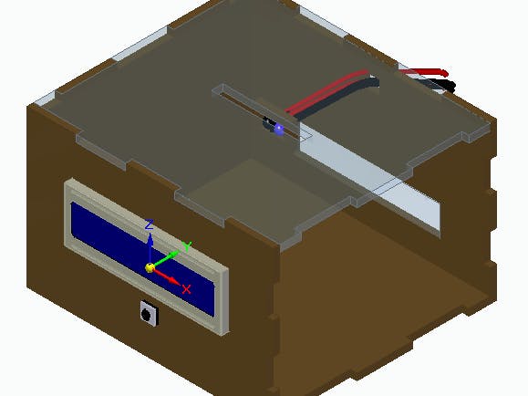
}For this project, a proper case was developed, which will receive the TCRT5000 reflective optical sensor, the LCD display, and the push button, leaving only the Arduino Uno pins to connect, so that it can be used in a didactic way, as shown in Figure 6.
From the assembly of the circuit and the programming of the Arduino Uno, it is possible to fix the LCD display in front of the didactic case, as well as to attach the reflective sensor in the upper region of the cover by means of small support at the entrance of the coins.
The push-button was fixed just below the LCD and, thus, right after the coins are placed, they can be removed through a small door at the back of the didactic safe, as shown in Figure 7.
In the same way that the rear region has a hole for the exit of the wires from the reflective sensor, the side region also has a hole for the exit of the wires from the LCD display, as well as the push-button.
The illustrative images of the didactic safe have some transparent regions in order to better understand the internal structure of the case.
Next, we will present the PCBGOGO Printed Circuit Board for the cash safe.
The PCBGOGO Printed Circuit BoardThe printed circuit board was developed to control the design of the cash safe. The figure below shows the printed circuit board in 3D.
This PCBGOGO Printed Circuit Board was developed through the electronic schematic presented below.
Therefore, from the development of this project, it was possible to know the structure of the TCRT5000 reflective optical sensor with transistor output and understand its operation, in addition to analyzing the communication with the Arduino Uno through the developed program.
As the sensor emits infrared light through the LED, and then the reflected light activates the phototransistor, it is necessary that the analyzed object, which in this case was the 1 real coin, must be at a distance of 5 mm to 10 mm of the sensor, in order to guarantee its detection, and in this way, the main components of the didactic safe were adapted to a didactic case.
AcknowledgmentWe thank PCBGOGO Printed Circuit Board for supporting the development of this project.
We would also like to thank the Robô Lúdico school in Brazil.


Comments