

Hardware components | ||||||
 |
| × | 1 | |||
| × | 1 | ||||
| × | 1 | ||||
 |
| × | 2 | |||
 |
| × | 20 | |||
 |
| × | 1 | |||
| × | 1 | ||||
Software apps and online services | ||||||
| ||||||
| ||||||
| ||||||
Hand tools and fabrication machines | ||||||
 |
| |||||
In the twelve years I’ve spent in Shanghai, air quality has always been somewhat of a constant concern. This was especially bad in the middle years of my stay, when numerous cities in China struggled with ‘the smog’. It was around 2013-2014 when I witnessed some of the most polluted days of my life. The reported air quality index shot was not just hazardous (avoid all physical or prolonged activity outdoors)but also out of range (over 500). The smog had become so thick that it resembled fog, obscuring your vision beyond even 50 meters.
Around high school, one of my closest friends began working on a scalable air quality sensing unit that he set up with a cloud service to measure air quality around the school. At one point, I was asked to help them design a 3D printable case for their parts and PCB. My dad and I tinkered around with simpler air quality systems on Arduino, with cheaper sensors.
As a result, I found myself wanting to take a crack at a similar project. The rights to my friend's project are all reserved by my high school, so accessibility is a key focus here. Furthermore, many similar air quality sensing projects on Hackster take a less holistic approach and don't encompass as many facets of air quality as dust, CO2, TVOC, temperature, or humidity. In addition, it may be a nice thought more than anything, but the PocketBeagle has been relatively underutilized in this application and it's more open-source in nature than competitors such as, say, a Raspberry Pi.
With the PocketBeagle as a given for this project, I started researching on what sensors I should use for a CircuitPython implementation of an air quality, CO2, TVOC, temperature, and humidity sensing module. First, I thought of the GP2Y1014AU0F, a simple dust sensor that I've used with Arduino projects in the past. At this point in the project, low-cost was still a priority, but this goal was gradually eroded (an Arduino implementation is more suitable for minimizing cost anyways). Upon realizing that I could not realistically use a GP2Y1014AU0F for a CircuitPython implementation, I promptly switched over to a PMS5003 sensor (by Plantower), which was significantly more expensive but also far nicer.
For sensing CO2 levels, I settled upon a CCS811 as a device that could both sense CO2 without breaking the bank (or having to wait through several weeks of lead time). As a bonus, it could sense TVOC levels with minimal extra work. Finally, I picked out a DHT11 sensor for temperature and humidity, also taking low cost into account. However, I faced significant difficulties trying to detect the sensor (trying multiple GPIO pins) in a CircuitPython implementation, and switched to a AHT10 sensor which was still on the cheap side while being capable of I2C data transmission (which made for an easy implementation).
Finally, I ended up choosing a 2.2" 18-bit color TFT LCD display that was branded and transplanted onto a breakout board by Adafruit. It's fairly large and has decently robust graphical rendering capabilities for it's price, although it was somewhat overkill for this project.
Some other goals such as uploading readings to a cloud database (using an additional USB connected WiFi module) were considered, but could not be implemented by the project deadline.
Build InstructionsWiring:
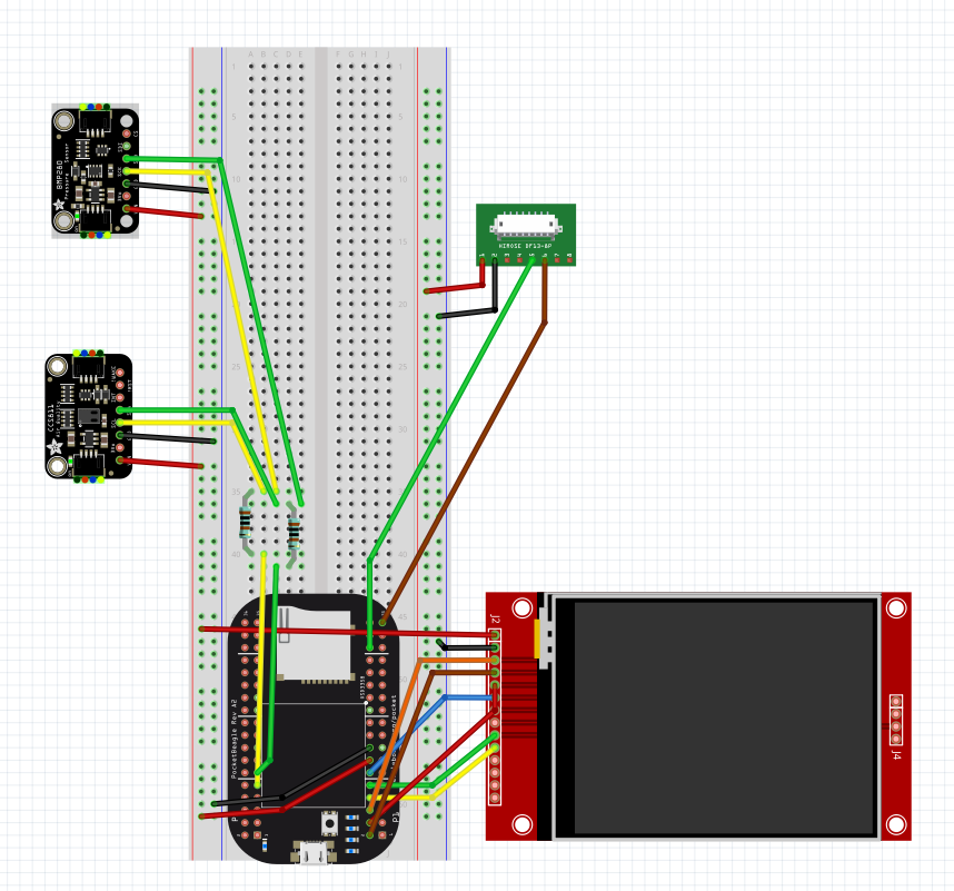
Note: The PocketBeagle used in this project has had its P1 VBUS and VIN pins solder bridged, in addition to its DN and DP pins. Refer to the below wiring diagram to clarify confusion at any point (also acknowledge that the SPI display below is not the exact same as the one used in this procedure).
First, set up the power rails on the breadboard, using one for 3.3V power and the other for 5V power. Connect the positive rail of one side of the breadboard to 3.3V, the ground to a ground on the PocketBeagle. Connect VOUT to the other power rail for 5V (assuming a 5V power supply), then either the same GND from the other rail to GND on the 5V rail, or to the other GND on the PocketBeagle.
Connect the 2.2" screen (or any similar screen) with the following:
- VIN: 3.3V rail
- GND: GND
- CLK: CLK (P1_8)
- MISO: MISO (P1_10)
- MOSI: MOSI (P1_12)
- D/C: GPIO89 (P1_4)
- CS: GPIO5 (P1_6)
- RST: GPIO87 (P1_2)
Wire up the I2C1 Bus (P2_9 = SCL and P2_11 = SDA) to share between the CCS811 and AHT10 sensors by leading SCL and SDA lines onto the breadboard and off into separate 1k ohm pull-up resistors. Connect four additional wires, two for each pulled up SCL or SDA line respectively.
Wire up the AHT10 and CCS811 sensors with VCC / VIN connected to 3.3V, GND to GND, SCL to SCL, and SDA to SDA.
In my personal project, I ordered a cheaper PMS5003 which had unlabelled terminals and only came with a connector. I cut off one end of the connector to resolder with jumper wire ends, but the wiring is the same if you were to use a breakout board:
- VCC to 5V rail
- GND to GND
- TXD to RX (P1_32)
Which concludes all the wiring! Plug your PocketBeagle in (and immediately unplug if it doesn't power on, then recheck your wiring for shorts).
Code:
Various libraries need to be installed for this project to function. All of the instructions assume a sufficiently updated Debian image is being used on your PocketBeagle. For guides on connecting to the internet and similar, refer to beagleboard.com.
Run the following commands on your Cloud9 workspace to install all the required libraries system-wide. Save for apt-get update, the above installations should all be fairly small and install within minutes.
sudo apt-get update
sudo pip3 install --upgrade Pillow
sudo pip3 install adafruit-circuitpython-busdevice
sudo pip3 install adafruit-circuitpython-rgb-display
sudo apt-get install ttf-dejavu -y
sudo apt-get install libopenjp2-7
sudo pip3 install adafruit-circuitpython-pm25
sudo pip3 install adafruit-circuitpython-ccs811
sudo pip3 install adafruit-circuitpython-ahtx0
The code attached below can be saved onto your Cloud9 workspace either through manual installation and dragging or dropping, or instead:
git clone https://github.com/Flygonial/ENGI301
This should clone the entirety of my workspace repository and also include the rest of my reference code and testing code, however, so it may be redundant. Do not use my run file without the rest of the paths factored in. If you want your project to run on start-up, my work is not the best place to look. Instead, create your own script of:
cd <run directory>
./configure_pins.sh
PYTHONPATH=<any paths needed> python <main_python script>.py
Save it all into a.sh file named 'run'. Write a configure_pins file specifying to your particular configuration of wiring. Of course, remember to call the file with elevated privileges (the below line in bash would also be how you run the file manually, if you're in the right directory), as Linux OSes don't play nice with serial:
sudo python3 air_quality_module.py
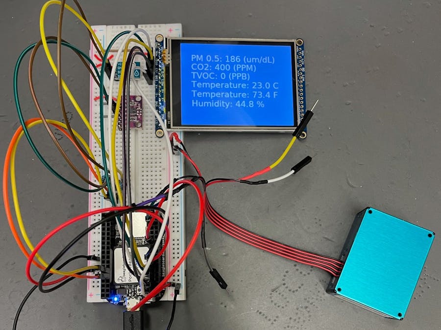
This should run the script! It may take a few seconds before the screen refreshes and begins displaying readings. Ideally, it'll function something like this:
Unfortunately, there is still one major issue with the functionality of this project in my implementation: getting readings from the PMS5003. Despite my pm25 library still including a merged 2020 fix that aggressively queries the sensor to recover from a failure to read from the sensor, I have not personally been able to get readings from the sensor except for very short, intermittent moments. Because of this, all measurements of larger particles (PM1.0 and above) are effectively meaningless, either 0 or very low, as no time has been given for such readings to stabilize. The sensor seems to return real measurements for PM0.3 and PM0.5, but with how many issues are being faced, the reliability of these measurements can be questioned as well.
Thus, I implemented my main loop to not display a reading for PM0.5 initially, then only update when a valid reading comes in (and leave that reading there until a new valid reading comes in). This is really just a workaround at this point, though the AHT10 and CCS811 sensors seem to work fairly well. The above video is close to a best-case scenario, it is not unlikely for the PM0.5 reading to stay on WAIT for upwards of 30 seconds to a minute.
At the very least, PM0.5 is a workable proxy for air quality, as it is generally considered the minimum size particle that gets trapped in your lungs and can cause long-term or short-term damage (depending on the time and acuity of exposure).
Future Improvements:
Though the system is currently in a good place for measuring eCO2, TVOC, temperature and humidity levels, the PM2.5 (and etc) implementation needs improvement. This is a fairly significant drawback as it is one of the most vital proxies for evaluating overall air quality in everyday life. The temperature and humidity can be told just from feel and one can intuitively tell when either would be a health risk to them. The CO2 and TVOC sensors are fairly good in this regard at alerting you to something you may otherwise not be aware of, but of course, in the future, I would ideally:
- Improve the dust particle sensing capabilities of the unit. Trying out a PMSA003I sensor may be something to try instead, as it communicates with I2C logic instead (eliminates the need for elevated privileges, and may play nicer).
- Properly implement a run-on startup setting: I have not truly been able to figure this out and need to set up more files such as configuring pins.
- Design a PCB and or a case for better packaging of the project. The side of the project can be significantly cut down upon in this case, and it'll be sure to be an aesthetic improvement.


_3u05Tpwasz.png?auto=compress%2Cformat&w=40&h=40&fit=fillmax&bg=fff&dpr=2)
Comments