

Hardware components | ||||||
| × | 1 | ||||
 |
| × | 1 | |||
| × | 1 | ||||
Software apps and online services | ||||||
 |
| |||||
Hand tools and fabrication machines | ||||||
 |
| |||||
It all started when I came across this project where a guy was using LoRa radios and Arduinos to send messages to an old Motorola Advisor Pager... So my thought was, what if it could be blue tooth... it would make a cool/retro messaging device. Imagine someone sending you a text and your pager goes off and everyone stares at you while you pull the pager out and look at the message, fun at partys and keeps people guessing. So I set out to make it a reality....
If you are planning on doing this project, I would suggest getting more than one of each Arduino. They are cheap and you can do testing with ease as apposed to trying to test with an Arduino that has no headers on it. The Arduino Pro Mini and the ESP32C6 come in packs of 3 typically, so I would suggest going with that. The Seeed XIAO ESP32C6s are a little more expensive than normal, but there is the knock offs that will work just as well.
Step 1: The PagerThe most compatible pager is the Motorola Advisor. This pager can be found all over Ebay and maybe other auction style sites, and probably Face Book market place. The pager should not run you more than 30 dollars. There is many flavors of this pager which is mostly just re-branding from other companies, but if it looks like the one pictured above, this is the correct pager. Before you make your purchase, make sure the pager fires up and the screen works completely (no lines through it, etc..). If you are lucky, you might be able to find one where the person knows the capcode of the pager and that its set to 512bps. (if this is not available, its not a loss cause, this can be pulled from the pager).
There are two other pages I was able to get functioning which is the Motorola Advisor II and the Unication E3 but for the sake of simplicity, we will stick with the Advisor for this project. (Pretty much any POCSAG pager at 512bps will work, but you will have to figure out where to tap in to send the signal from the Arduino).
Step 2: Pager PrepNow we come to probably the biggest pain part of this project, prepping the pager. If you do not know the capcode of the pager or you need to set the pager into 512bps, you will need to program the pager. This requires a serial to TTL converter and some custom software. Luckily, you will need a USB to TTL device to program the Arduino Pro Mini and the programming software is readily available all over the net, just search for Motorola Advisor programming software, but getting this software to work is another story. This is an old DOS program and will not run on any modern computer.
When I say old, I mean windows 98 old. It has to be run in a real DOS environment, anything Windows XP and higher is either emulated inside windows or it won't run at all. For this reason, I used an old Core2Duo I had sitting around and installed Freedos on it. Some folks have had success using a virtual machine type setup like virtualbox and putting Freedos on it. Getting this setup is beyond the scope of this project, but a simple search for "programming Motorola Advisor pager" will yield many pages of folks who have successfully programmed their pager.
Once you are able to access the pager, we just need to get the capcode and set the coding format to POCSAG 512. So fire up the program
Use whatever method you have come up with to connect to the pager and hit F3 to read the pager
If the coding format says anything other than POCSAG 512, hit the down arrow to highlight that spot and then hit the space bar to change it. Be sure to write down the capcode. To move to the next screen, hit the PG DWN button on the keyboard. On the 4th screen you will come across an option for international prompts. This option will allow you to set a custom start up text like I did with FletchFXIOT.
If you set this to custom and hit PG DWN you can change the text to whatever you want. When done, hit PG DWN again to get to the last screen. Do not change anything else.
Now connect the pager again and hit F4 to program with the new information. As a final check, hit F10 and go back to the main menu and have the program read the pager again and be sure that the 512bps and the capcode are correct. After verifying, you can close down this program the pager is ready.
Step 3: Pager DisassemblyThere are no screws holding the pager together, its actually a pretty ingenious design. Turn the pager so the buttons are too your left and the bottom is too the right and you will see a rectangle piece with lines around all 4 sides. This piece is actually designed to slide out of that place. I have seen people use a screwdriver at the top to pry it up, but this is not really necessary in my opinion and could potentially break the clips.
Lift at the top just a little, and push from the bottom to slide it out of its locking place. Fingernails seem to do the trick every time.
Now that the clip is off, it will have a small catch at the bottom right above the positive side of the battery. If you slip the tip of a screw driver under the battery door latch and push down on the back of the screw driver it should pop the case apart.
Now the pager is open and we are ready to extract the radio.
The board with the NRF41010 on it is what we are after, this is the radio board that we are going to emulate with the Arduinio Pro Mini. This only has a small header on it so it should pull straight out of the pager.
You may or may not have to prep the lid, mine had this grey rubber piece just below the motor, but I need that space for the step down converter. This little piece is just held in place with a simple post, it will also just pull straight off.
But now there is a post in the way, this area needs to be flat to accommodate the step down converter, nippy cutters will take care of that.
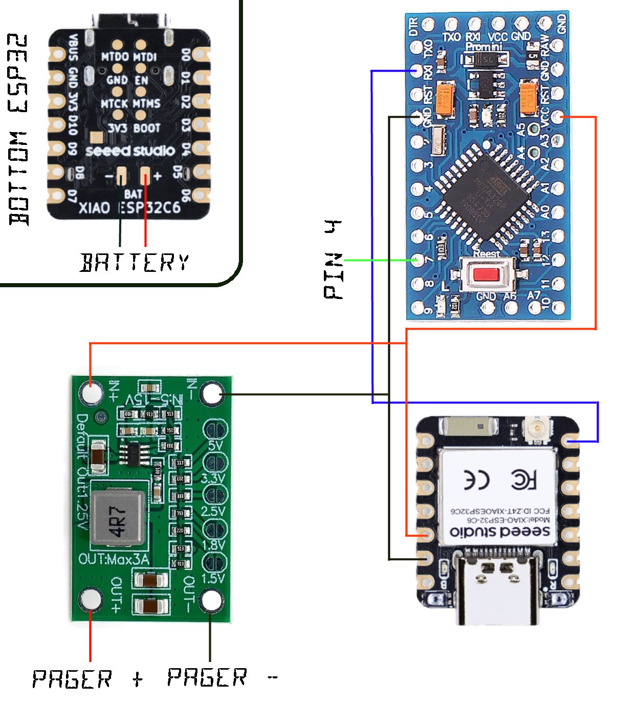
Lastly we need to identify the pin that we will be sending the POCSAG message to, this is pin 4 on the header we pulled the radio from.
You have your choice of leaving the pins in place and attempting to solder a wire to it, or just removing all the pins except the one we need which is what I decided to do (no need to solder anything yet, just showing the pins cut from my finished pager).
Pager prep is complete. At this point, the pager should be set to 512bps, you know what the capcode is and we have exposed the receiving pin. You might want to put a battery in it and test and make sure its still working. The radio board is not required to fire up the pager and unless you have a use for the radio it can be trashed or put in a parts bin for later.
Step 4: Arduino Pro Mini testIf you took my advice and bought more than one of each Arduino, its time to throw some headers on one of the ESP32C6s and on one of the Arduino Pro Minis.
Download the AdvisorRadio.ino file, change the capcode at the top to your capcode and load it onto the Arduino Mini Pro. Hook up the ground wire and pin 7 to the pager. Ground goes to the ground of the battery and ping 7 goes to pin 4 on the pager.
I used some black tape and covered where I removed the other pins, there is some voltage on one or two of those that if they get grounded will turn the pager off and might possibly harm some of the chips, so best to keep them covered.
If the sketch loads fine and you get this message in your serial monitor
You should be ready to test to see if the pager itself is able to receive a POCSAG messages from the Arduino. Just type test and hit enter.
The POCSAG will send and the pager should beep and show the message on the screen for a couple of seconds then go back into sleep mode. If this worked you are ready for the next step, if it did not, check the connections, the ground may have slipped away from the battery, etc..
Step 5: ESP32C6 BLE testNow that we have the Arduino talking to the pager, we can move onto testing the ESP32C6. Download Chronos onto your android device, this can be found in the play store.
Sorry IPhone users, there is no version of this at the moment for IOS. Once installed, download the ble_pager.ino from the code area and the Chronos-ESP32 library and add it to your Arduino IDE. Other libraries you will need are NimBLE and ESP32Time which both should downloadable through the library manager. Compile and Load the ble_pager.ino onto the ESP32C6. Make sure the ESP32C6 is up and running before starting the Chronos software.
Open Chronos on your android device, it will ask for a bunch of access to the phone just like if you were installing a smart watch since this software is essentially for a smart watch. Once it has the correct permissions, it should step you through the initial setup which will involve finding the watch. When it goes to pair process, look for Advisor in the list.
Once you pair, the ESP32C6 should show "Phone connected" on the serial monitor. and the top of Chronos should show the watch connected
There is various settings in Chronos, make sure you go into the apps section and be sure you have all the notifications turned on that you want to receive on the pager or they will not show up.
Step 6: Testing The ProcessAt this point, we can wire the ESP32C6 to the Arduino Pro Mini and watch the action happen. There is only 3 connections that need to go between the two. D6 on the ESP32C6 goes to RX1 on the Arduino Pro Mini. The 3.3v on the ESP32C6 goes to VCC on the Arduino Pro Mini and of course ground between the two on one of the ground pins. Pin 7 on the Arduino Pro Mini should still be connected to pin 4 on the pager and also grounded. Do no plug the Arduino Mini Pro in at this point, it will be powered by the ESP32C6. Plug the ESP32C6 into a USB port and wait for a minute or two for it to connect to the phone.
Once the ESP32C6 connects to your phone, you are ready. Open Chronos and go to the menu at the bottom with the picture of the bell. Push the self test button on that screen and it should send a page through to the pager...
Step 7: Putting it all togetherNow that we know everything works, we can put the code on the Arduinos without headers. If you are wondering how I did this with the Arduino Pro Mini since there is no headers on the back to hook the USB converter too, well I just put the header in its place without soldering it and when I went to program it, I just put a little pressure on it so it made a good connection.
Once the programming is complete, the parts can be laid out in the lid. I actually put double sided sticky tape in the lid and just secured them in. I soldered the wires for the battery connection on the bottom of the ESP32 first to get that out of the way, then laid everything on the sticky tape and made sure that I could close the case with all the parts in it.
Obviously there is plenty of things that can be added to this to make it more robust, so leave yourself some space in case you come up with a new idea to add to it. Though I soldered my Arduino Pro Mini in the other way, I would suggest putting the header side up at the top so you can get to the pins should you want to flash a new sketch on it later if you come up with an idea to add to it.
Dont forget to solder the pad on the step down converter over top of the 1.5v, the default its 1.2v which will still run the pager, but since its 1.5v standard, I soldered the pad. The last piece of this puzzle is the battery connections. I opted to use a 3.7v 10440 battery. This battery is slightly longer than a typical AAA battery that was used in the pager.
Since the pager is designed to run on 1.5v, we have to do some modification to get everything to work together, so the + connection will need to be removed. The white battery holder is actually held in by the battery connectors, I just cut the positive connection at the base and then soldered the + out from the converter to make the connection.
The negative side can go directly to the ESP32 as it will supply the ground to the step down converter. The white battery holder is slightly to short to accommodate the 10440 battery, it can either be modified, or you can print one out if you have access to a 3D printer. STL file is linked below.
This will slide under the negative spring and cover the 1.5v + connection.
And then using the pieces from the portion I cut off, I created a positive battery connection which gets connected to the positive on the bottom of the ESP32 for the battery.
Connections completed.
Install the battery.
And give it a try, start up Chronos and make sure its paired to the pager and send a test message.
Enjoy your IOT Device.
Step 8: Things to doThe battery is only 950mah, their may be others with higher ratings, but I wanted one that would fit as the AAA did. That being said, the battery will probably only last a few hours with both Arduinos running full power and the BLE on. I am sure there is a way to put both in a sleep state so that the BLE can wake the ESP32 and then the ESP32 can wake up the Arduino Pro Mini, this would probably make it last much longer.
Using two Arduinos is the only option I could come up with as the POCSAG code will not run properly on anything faster than 8mhz. So maybe re-write the code so it will run on faster hardware but still send the POCSAG correctly. That would eliminate some of the power draw.
Possible other options might be a step counter or other sensors like a smart watch might have. Since Chronos is designed for smart watch capability, there is plenty of other things that are possible.
Thanks for checking out my project, if you attempt it, please let me know and comment.


_3u05Tpwasz.png?auto=compress%2Cformat&w=40&h=40&fit=fillmax&bg=fff&dpr=2)
Comments