Since the end of the 90's, a phenomenon known as Colony Collapsse Disorder, among honey bees, has been observed. In addition, new weakening factors have appeared, such as vespa velutina (commonly called Asian hornets) and varroa (a parasite causing malformations). Climate change, the use of pesticides and the theft of hives do not help their case. This phenomenon also impacts us, because our survival depends on the survival of pollinating insects.
As part of our second year of engineering degree at Polytech Sorbonne, in Electronics and Computer Science, and in collaboration with the Plaisir Village Animation association, we have created a connected system for a beehive monitoring. Weight, temperature, humidity and luminosity data are sent through LoraWan and are processed on TTN and Beep to be shown to beekeepers.
Step One : Designing of the ProjectHere are the different components of our project.
The Power module is comprised of a 3.7V, 1050maH battery, along with a solar pannel and a LiPo Rider Pro which ensures the charging of the battery through the solar pannel, and the alimentation of the system. There are also two 3.3V voltage regulators. The first one powers the system and is connected to a voltage divider, that will allow us to measure the percentage of the battery. The second one aims to limit the overall consumption of the system, by turning it on and off to shut off all the sensors that can't be shutdown through software.
The sensors included in our project are the following :
- A voltage/current sensor (INA219), that will measure the level of sunlight by connecting it to the solar pannel.
- Two temperature and humidity sensors (DHT22), that will measure the temperature and humidity both inside and outside of the hive.
- Two or three temperature probes (DS18B20) that will measure the temperature in several places of the inside of the hive.
- A weight sensor, comprised of a load cell and an amplifier (HX711), that will measure the weight of the hive.
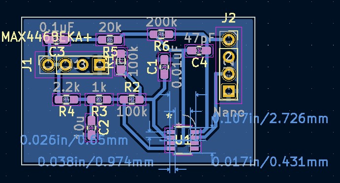
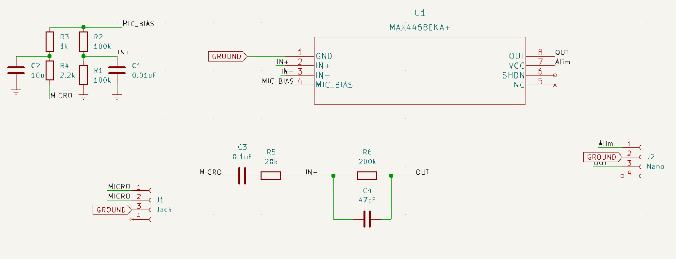
- An audio sensor, comprised of a microphone and an amplifier, that will be used to measure at which frequencies the bees are the most active.
The communication module is provided by the LoRa-E5 module, that is connected to the Arduino with the RX and TX pins. It allows the system to communicate data OTA, by using Lorawan.
Finally, the microcontroller itself (the Nano 33 BLE Sense), whose wiring with the other modules are detailed on the image provided.
You may test the system before going to the next step, by wiring it with a breadboard.
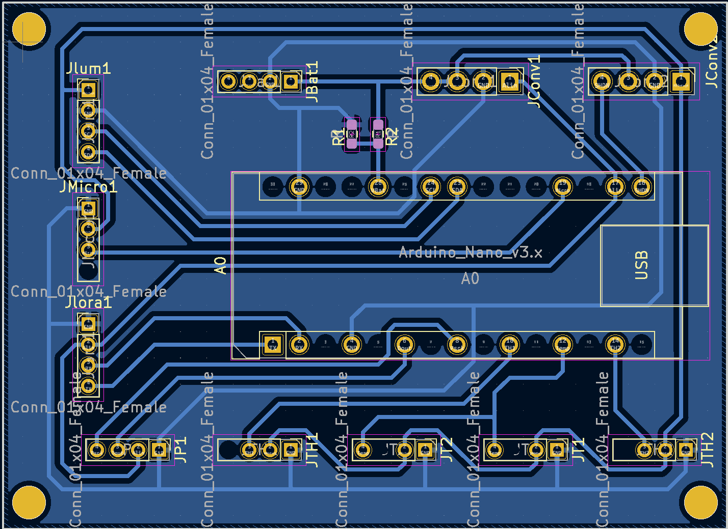
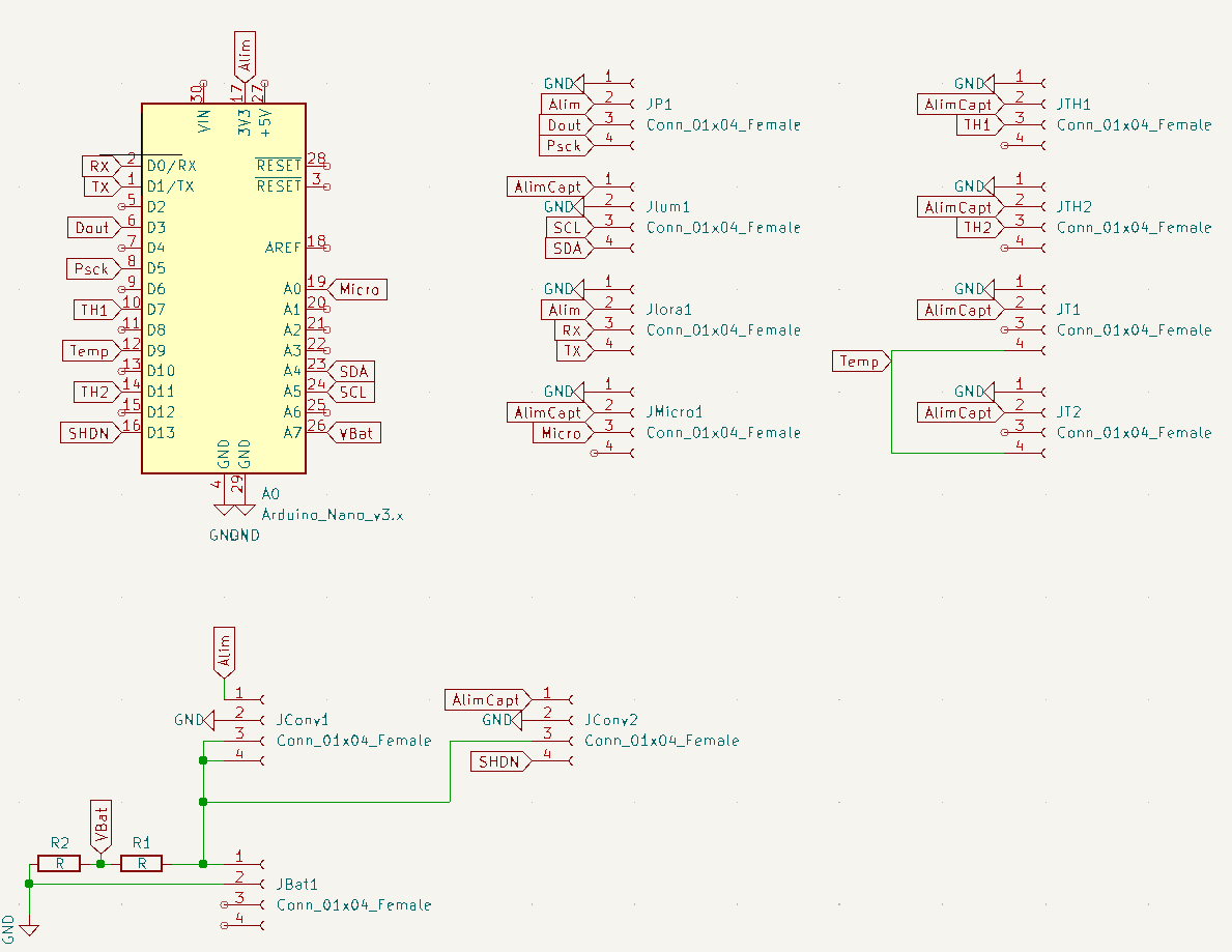
Step Two : Printing the PCBsThe next step is to print the PCBs included with this project. Each of the connectors should be soldered with female grove connectors. They will allow an easy connection between the different sensors and the Arduino. The resistors can be replaced with SMD resistors, though they are a tad harder to solder.
Step Three : Connecting to The Things Network and UbidotsTo visualize the data, we need to send them OTA (over the air) with little to no additionnal consumption. To do so, we decided to go with the LoraWan protocol.
Connecting to TTNCreate an account on TTN: https://account.thethingsnetwork.org
To create an account on "The Things Network", you may use a disposable email address such as the one proposed by Yopmail. Yopmail, for Your Own Protection mail, is a temporary and free email address that does not require a password. You may also use your own mail address.
On the console, select "Go to application"
Create a new application "Add application"
Give it a name and click on create application.
Go to " End devices ", create a new device by clicking on " Add end device ".
For the selection of the end device, in the Brand field, select Seeed Technology, then the model " Seeed Studio lorawan Dev kit " and finally the Profile " EU_863_870 "(Or any other depending on where you are located).
For the 2nd part " Enter registration data " :
Frequency plan: Europe 863-870 MHz (SF9 for RX2 - recommended) (again, choose the most adapted one depending on your location)
AppEUI : Fill with zeros for now
DevEUI : Generate
AppKey : Generate
End device ID : what you want !
And click on the Register end device
Testing the connection with ArduinoYou may test the connection to TTN with the following code. You will need to adapt the code to your own parameters, by changing the following lines with your own values : line 37, line 40, line 41 and line 42.
static char recv_buf[512];
static bool is_exist = false;
static bool is_join = false;
static int at_send_check_response(char *p_ack, int timeout_ms, char *p_cmd, ...) {
int ch;
int num = 0;
int index = 0;
int startMillis = 0;
memset(recv_buf, 0, sizeof(recv_buf));
Serial1.write(p_cmd);
delay(200);
startMillis = millis();
do {
while (Serial1.available() > 0) {
ch = Serial1.read();
recv_buf[index++] = ch;
delay(2);
}
} while (millis() - startMillis < timeout_ms);
if (strstr(recv_buf, p_ack) != NULL) {
return 1;
} else return 0;
}
void setup() {
delay(3000);
// put your setup code here, to run once:
pinMode(12, OUTPUT);
digitalWrite(12, HIGH);
//début du serial1 pour la communication LoRaWAN
Serial1.begin(9600);
//connexion LoRaWAN
if (at_send_check_response("+AT: OK", 100, "AT\r\n")) {
is_exist = true;
at_send_check_response("+ID: AppEui", 1000, "AT+ID\r\n");
at_send_check_response("+MODE: LWOTAA", 1000, "AT+MODE=LWOTAA\r\n");
at_send_check_response("+DR: EU868", 1000, "AT+DR=EU868\r\n"); //change if needed
at_send_check_response("+CH: NUM", 1000, "AT+CH=NUM,0-2\r\n");
at_send_check_response("+KEY: APPKEY", 1000,
"AT+KEY=APPKEY,\"5096ECB9BD2700F2C039F5A04351B770\"\r\n"); //change with your own
at_send_check_response("+KEY: DEVEUI", 1000, "AT+ID=DEVEUI,\"ABC3E554E09DF7E6\"\r\n");//change with your own
at_send_check_response("+KEY: APPEUI", 1000, "AT+ID=APPEUI,\"0000000000000000\"\r\n");//change with your own
at_send_check_response("+CLASS: C", 1000, "AT+CLASS=A\r\n");
ret = at_send_check_response("+PORT: 8", 1000, "AT+PORT=8\r\n");
delay(200);
is_join = true;
//économie de batterie en éteignant la led PWR
digitalWrite(LED_PWR, LOW);
} else {
is_exist = false;
}
}
void loop() {
// début envoi
if (is_exist) {
int ret = 0;
if (is_join) {
ret = at_send_check_response("+JOIN: Network joined", 12000, "AT+JOIN\r\n");
if (ret) {
is_join = false;
} else {
at_send_check_response("+ID: AppEui", 1000, "AT+ID\r\n");
delay(5000);
}
} else {
char cmd[128];
sprintf(cmd, "AT+MSGHEX=%04X\r\n", 10);
at_send_check_response("ACK Received", 5000, cmd);
delay(30000);
}
} else {
delay(1000);
}
}
This code should send simply send the value 10 to TTN every 30 seconds. To visualize the data sent, you will need to go on your TTN account's console, then to "End Devices", then select your device and finally go the "Live data" tab.
To better visualize the data you will send, you may need to use another third-party app. Ubidots is a good free alternative, though it is limited to only 10 different data if you create a free STEM account. Here, you can follow the tutorial to add the TTN plugin to your Ubidots account. You will then need to modify the default decoder. To do so, select "Devices", then "Plugins", then click on "The Things Stack", then go to the "Decoder" tab, and copy/paste the following code :
function format_payload(args){
var ubidots_payload = {};
// Log received data for debugging purposes:
// console.log(JSON.stringify(args));
// Get RSSI and SNR variables using gateways data:
var gateways = args['uplink_message']['rx_metadata'];
for (const i in gateways) {
// Get gateway EUI and name
var gw = gateways[i];
var gw_eui = gw['gateway_ids']['eui'];
var gw_id = gw['gateway_ids']['gateway_id'];
// Build RSSI and SNR variables
ubidots_payload['rssi-' + gw_id] = {
"value": gw['rssi'],
"context": {
"channel_index": gw['channel_index'],
"channel_rssi": gw['channel_rssi'],
"gw_eui": gw_eui,
"gw_id": gw_id,
"uplink_token": gw['uplink_token']
}
}
ubidots_payload['snr-' + gw_id] = gw['snr'];
}
// Get Fcnt and Port variables:
ubidots_payload['f_cnt'] = args['uplink_message']['f_cnt'];
ubidots_payload['f_port'] = args['uplink_message']['f_port'];
// Get uplink's timestamp
ubidots_payload['timestamp'] = new Date(args['uplink_message']['received_at']).getTime();
// If you're already decoding in TTS using payload formatters,
// then uncomment the following line to use "uplink_message.decoded_payload".
// PROTIP: Make sure the incoming decoded payload is an Ubidots-compatible JSON (See https://ubidots.com/docs/hw/#sending-data)
// var decoded_payload = args['uplink_message']['decoded_payload'];
// By default, this plugin uses "uplink_message.frm_payload" and sends it to the decoding function "decodeUplink".
// For more vendor-specific decoders, check out https://github.com/TheThingsNetwork/lorawan-devices/tree/master/vendor
let bytes =  Buffer.from(args['uplink_message']['frm_payload'], 'base64');
var decoded_payload = decodeUplink(bytes)['data'];
// Merge decoded payload into Ubidots payload
Object.assign(ubidots_payload, decoded_payload);
return decoded_payload;
}
function decodeUplink(bytes) {
var decoded = {};
decoded.weight = (bytes[0]<<8 | bytes[1])/100 - 5.5;
if (decoded.weight<0) decoded.weight = 0;
decoded.temperature_DHT1 = ((bytes[2]<<24)>>16|bytes[3])/10;
decoded.lum = 5*Math.pow(10,((bytes[4]<<8|bytes[5])/100-0.4));
decoded.battery = (bytes[6]<<8|bytes[7]);
decoded.humidity_DHT1 = (bytes[8]<<8|bytes[9])/100;
decoded.temperature_Sonde1 = ((bytes[10]<<24)>>16|bytes[11])/10;
decoded.temperature_Sonde2 = ((bytes[12]<<24)>>16|bytes[13])/10;
decoded.temperature_DHT2 = ((bytes[14]<<24)>>16|bytes[15])/10;
decoded.humidity_DHT2 = ((bytes[16]<<24)>>16|bytes[17])/100;
decoded.s_bin098_146Hz = (bytes[18]<<8|bytes[19])/100;
decoded.s_bin146_195Hz = (bytes[20]<<8|bytes[21])/100;
decoded.s_bin195_244Hz = (bytes[22]<<8|bytes[23])/100;
decoded.s_bin244_293Hz = (bytes[24]<<8|bytes[25])/100;
decoded.s_bin293_342Hz = (bytes[26]<<8|bytes[27])/100;
decoded.s_bin342_391Hz = (bytes[28]<<8|bytes[29])/100;
decoded.s_bin391_439Hz = (bytes[30]<<8|bytes[31])/100;
decoded.s_bin439_488Hz = (bytes[32]<<8|bytes[33])/100;
decoded.s_bin488_537Hz = (bytes[34]<<8|bytes[35])/100;
decoded.s_bin537_586Hz = (bytes[36]<<8|bytes[37])/100;
decoded.temperature_Sonde3 = ((bytes[38]<<24)>>16|bytes[39])/10;
return {"data": decoded};
}
module.exports = { format_payload };
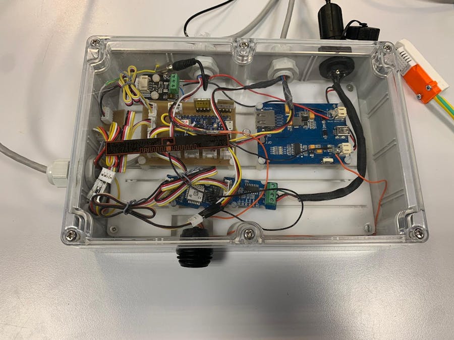
This code allows Ubidots to decode the data sent by TTN in human-readable data.This final steps is the design of the box that will contain our system, to protect it from bad weather and from the bees at the same time. You may choose a box of your choosing, however, you must be able to pierce it in several places to lengthen the differents sensors that need to be outside the box, such as the temperature sensors and the humidity ones. You will then have to use some long ethernet cables to solder your sensors to, like you can see on the photo.
In order to position the various boards and PCBs, we decided to drill a POM plate using a laser engraver. Here is a sketch and the 3D model of our plate:
We decided to drill lines on our plate. These lines have different spacings. By doing this, we can move our cards as we want to have a better layout or we can add new cards easily with this mechanism.
Now, all you need to do is find a hive to connect your system to, and watch in real-time the state of your bees.




_4YUDWziWQ8.png?auto=compress%2Cformat&w=48&h=48&fit=fill&bg=ffffff)




_Ujn5WoVOOu.png?auto=compress%2Cformat&w=40&h=40&fit=fillmax&bg=fff&dpr=2)


Comments