

Hardware components | ||||||
 |
| × | 1 | |||
 |
| × | 1 | |||
| × | 1 | ||||
| × | 1 | ||||
| × | 1 | ||||
| × | 1 | ||||
 |
| × | 1 | |||
 |
| × | 8 | |||
Software apps and online services | ||||||
 |
| |||||
 |
| |||||
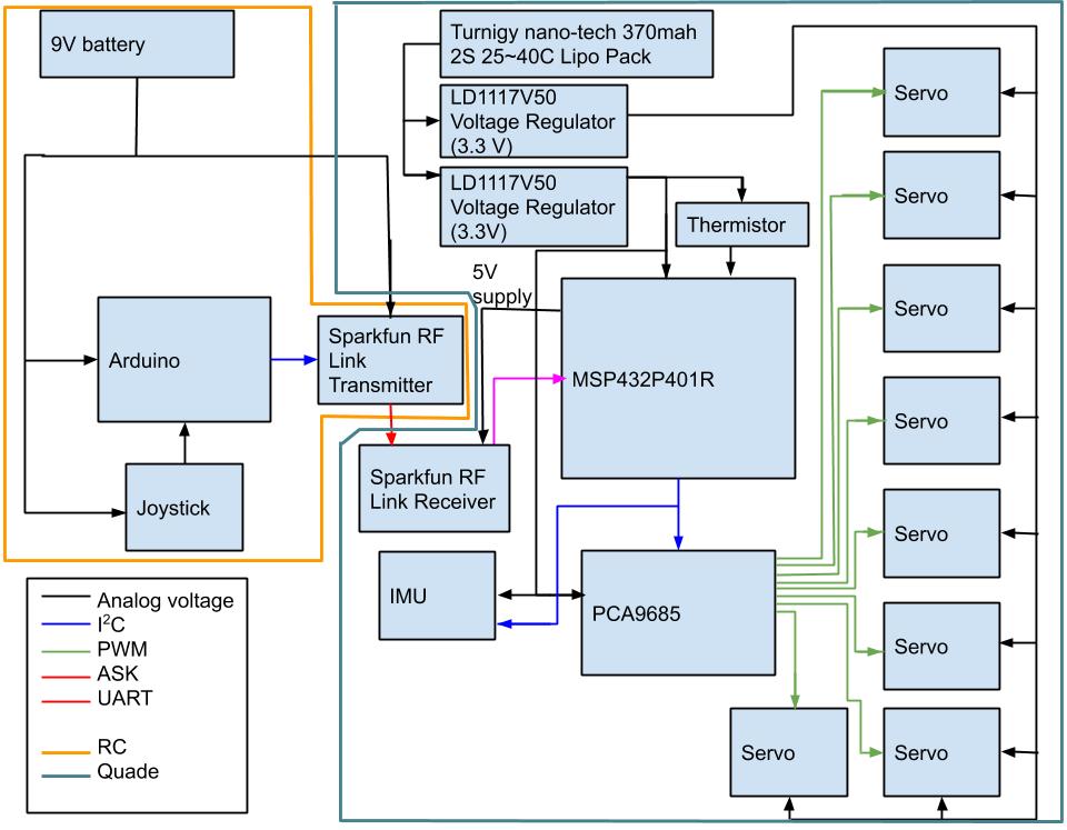
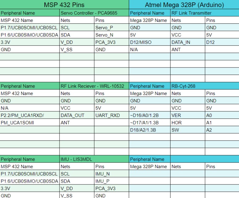
For our final project, we programmed Quade to move in different directions based on input from a remote control with a 2-axis analog joystick. Quade is controlled using C code on the Texas Instruments MSP432P401R Simplelink LaunchPad. This microprocessor receives wireless ASK input from the remote control using radio frequency (RF) transmitter and receiver links. For the remote control we will use C# within the Arduino IDE, and we have a joystick that outputs analog voltages (one each for the vertical and horizontal position) which are converted within the Arduino Uno board to digital values which we then output to the MSP432 to control the movement of Quade.
Project ScopeFor this project, we configured the MSP432P401R Simplelink LaunchPad to determine the movement of Quade. The Arduino Uno reads two analog voltages from a joystick, one for each axis, and converts those analog signals within the Arduino Uno to digital values. These values are then transmitted via UART to the Sparkfun RF Link Transmitter, which sends it to the Sparkfun RF Receiver via ASK. Upon receiving each value, the RF Link Receiver then relays the information via UART to the MSP432P401R, interrupting once each complete bit is received and storing the data for the positions of both axes in a buffer once it receives those data.
Within the MSP432, we created a Finite State Machine (FSM) with three different states, as can be seen in main.c in our GitHub repository:
- Neutral Position (0)
- Read data from Rx UART buffer, make calculations (1)
- Write data to servos (2)
When in Neutral Position, the MSP432 takes readings from the IMU via I2C and the servos sit idle. Once the button S1 is pressed, the FSM moves to State 1. Once in this state, the MSP432 reads RF Link Receiver data from the buffer. Next, it parses these data to determine the position of the joystick (up/down, left/right). Then, it sends I2C data to the PCA9685 to move the servos in a series of steps so that Quade will step in the direction that matches the joystick position.
Also, we use a thermistor along with the ADC on the MSP432 to acquire data for the ambient temperature. We then use this data to control the state and color of the onboard LEDs.
Functional Block DiagramRF Link Transmitter
The first thing tested and debugged was the analog signals from the two axis joystick. We accomplished this by creating the circuit (found in the transmitter schematics) on a breadboard and utilizing an oscilloscope to measure the output voltages based on the joystick’s movement. We found that the horizontal and vertical signals go from 0 to V_in linearly with ½ V_in for both the horizontal and vertical for resting value. The selector switch on the joystick is 0 volts resting and V_in when pressed.
Next, to test the values of the Arduino sketch and ensure the analog to digital converter (ADC) values were correct we utilized a serial write function from the standard Arduino library to display the values of the ADC to the screen over the serial monitor on the Arduino GUI. Once these values were confirmed to be accurate based on the joysticks position and voltage the UART transmitter was then debugged. Below are sections of the Arduino sketch which we debugged:
We used the logic analyzer on the Analog Discovery 2 to debug and test the UART transmission signals. The logic analyzer has a built in UART reader so the signal was quickly decoded using the UART reader and broken down by its components so that it was easily recognizable. When the output signals matched the ADC values we had confirmation that the transmitter was transmitting valid data from the joystick position.
RF Link Receiver
On the receiving end, the testing and debug was broken down into two parts. First, testing and debugging the UART configuration and second, testing and debugging the UART IRQ handler. We utilized the TI driver library to create a boilerplate UART configuration and IRQ handler which we then ran in debug mode to view how the control registers were configured by the driver library. This, along with the technical reference manual and data sheet made it easy to compare our UART configuration code to ensure it performed the same as the premade TI code. Once we confirmed that all the control registers were configured correctly we then shifted to the IRQ handler, shown below:
The easiest way to debug the IRQ handler was to utilize the Analog Discovery 2 (AD2) waveform generator to create a signal that was exactly what the transmitter should be sending to the receiver. This way any variables were taken out and a “clean” signal was given to the UART receiver pin on the MSP 432. With the generated UART signal on the UART receiver pin and the MSP in debug mode we then could step through the code and see the MSP 432 moving from an idle state into the IRQ handler function after it received valid UART data and passed a UART interrupt flag. Also, at the same time we could ensure that the data passed in the IRQ handler was the correct values generated from the AD2 waveform generator.
This method of testing ensured that the transmission of data from the joystick position to the values stored in the MSP 432 were confirmed to be valid and could be trusted to work under ideal conditions. For future testing we would then integrate the actual RF electronics and re-create the tests, then add conditions that would “break” the transmitter-receiver link until we found the working conditions. If these conditions were acceptable we could move on, if not we would systematically debug and change the design until it performed as needed.
Thermistor
The thermistor required several stages of debugging to insure everything was working properly. One of the first tests was the thermistor itself which just required measuring the resistance with a multimeter and applying heat to see if the resistance changed. Ensuring that the thermistor worked meant we could then create the voltage divider circuit to test the change in output voltage depending on temperature. We tested this using the 5V out from the MSP432 and probed the middle pin of the voltage divider using a handheld oscilloscope. By using a small space heater to apply a high temperature to the thermistor, we were able to see an increase in voltage meaning that the voltage divider was working. The next step to debug was the MSP432 code itself, which involved the debugger. When debugging the code, we monitored the value in the Registers: ADC14; ADC14MEM0; Here is where the hexadecimal value of the adcResult is stored. Upon converting from hexadecimal to decimal, we could then translate the value to an approximate temperature from our thermistor diagram table. We were then able to test how well the colors flowed by either using a blowing space heater or rubbing an ice cube on the thermistor to heat it up or cool it down. Our initial debugging found that as the lights lit up, they would then stay on so eventually all the lights would turn on if gone through each LED color combination. This was solved by including a couple lines of code that would turn off all the LEDs every time there was an interrupt so the colors were always current. Here is a section of the ADC14 IRQ handler which we debugged, including resetting all LEDs at the beginning of each iteration of the subroutine as well as setting the LEDs as determined by the ambient temperature:
One of the main challenges we had to first overcome was to decide on a project that was manageable based on the group's prior knowledge. In order to do this we had to evaluate everyone's strengths and weaknesses and ultimately decided to prepare a project that was more hardware based rather than software heavy. To complete this project in a timely manner and to full ability we then had to decide how to split the project into individual pieces and designate team members to these pieces based on their strengths. This was done by creating a Gantt chart where team members could choose pieces of the project they felt most comfortable completing. Another challenge that our group faced was integrating code created from other sources into our design in order to create our final product. To successfully integrate our code we had to first figure out how the code written by a different source functioned and what it was actually doing line by line. Once this was completed it was just a matter of adding or removing snippets of code to meet our design requirements.
Another challenge for our team was writing a UART driver for receiving ASK data on the MSP432 which was compatible with our custom Arduino sketch for transmitting those data. The different data packets for each joystick component were sent serially–vertical, then horizontal, then switch, two bytes each–and the start and stop signals were unique as well. To counter this, rather than using the RXBUF bit field within the EUSCI_A2 peripheral on the MSP432 (which we used for UART reception), we created a smaller state machine simply for receiving data and a custom buffer to hold those data. As a result, we are now able to parse those data once they are received from the RedBoard via the RF Link Transmitter and Receiver.
Trade StudyJoystick vs. Levers Trade Study
For our project we have decided to move Quade via joystick. The joystick will move Quade forward/backward in the x/y direction based on the input from the user. The main consideration for deciding whether to use the joystick or levers is the amount of time we have after creating the majority of the product. If we have enough time then we may consider switching over to a series of levers to move Quade. However, we also have to consider the cost, accessibility, and complexity of the levers if time is not an issue. To minimize the amount of time and issues with team members getting parts it is preferred to use the parts from the supplied kit. By using parts from the supplied kit this will also minimize the cost for the project. The complexity of using the levers also has to be considered because we have to make sure that we allow ourselves enough time to complete the design. If implementing the levers is very complex, then it may be too time consuming to finish before the due date. A decision to implement the levers will be made once we have finished the majority of the project with the joystick.
After looking at three solutions the choice that makes the most sense is to utilize a more basic and less complex device such as the RF Transmitter/Receiver since connecting it the the provided joystick with an arduino is simple and the cost and accessibility are still low. The drawback is more circuitry is needed to allow the receiver to communicate to the MSP 432, but that can be solved with the included logic converter. Looks like we have a winner!
For a wireless device to transmit and receive information, it needs an antenna to successfully work especially when the transmitter and receiver are further away from each other. However, there are several options when adding an antenna to a project. The antenna for the Tx and Rx can either be implemented as a:
- PCB trace
- Chip
- External wire (Whip)
A PCB trace will have a very low profile since it will sit on the PCB. However, designing a PCB trace antenna is quite complicated and can become very long at lower frequencies. PCB antennas have a good performance if properly designed.
Chip antennas are also on board the PCB and create a very low profile, however they are more expensive since they add to the material and mounting costs. The ACAG1204-433-T chip antenna for 433Mhz is $1.96 from Mouser electronics. They also do not have the best performance for the price and effort to include onto a PCB.
An external wire (whip antenna) takes up much more room than a PCB or chip antenna and a professionally made one is much more expensive with the cheapest one from Mouser electronics being $4.05. However, these antennas can be made easily by calculating the ¼ wavelength and using a simple wire. This option also has a much better performance than the PCB and chip antenna.
While it would be very neat to have a thin and sleek PCB transmitter and receiver without a wire sticking out, a simple external whip antenna would be much cheaper, easier to manufacture, and implement into the design of the Tx and Rx.
Wireless Communication Trade Study
For our project we have decided to use the base Quade as a platform to showcase remote control of Quade’s movements. This requires that a wireless transmitter and receiver is utilized. There are several options for small scale wireless transmitters and receivers. The primary three are:
- Wifi
- Radio Frequency
- Bluetooth
The main considerations for each of these will be cost, accessibility to team members, complexity, and compatibility. It is important to minimize costs, since we don’t have that Gucci grant money to run this project. Next, we want to maximize accessibility for each of the team members to utilize the component. Working with parts in the supplied kit or from local dealers is preferred over hard to find or long lead time parts. Minimizing complexity is important for this project because our digital logic and circuits classes have taken most of our mental bandwidth and if we use a highly complex system we might not make it to the end of the semester. Last, compatibility is important since if it doesn’t work with our board then it, well, doesn’t work.
WiFi:
Cost: This part is included in the kit, so no additional costs are incurred by group members, however it did cost $5.95 which is relatively inexpensive.
Accessibility: This is the most accessible part because it is already included in the kit that was distributed to each group member. We already have it!
Complexity: This is medium to high complexity because WiFi was not taught in class and creating a transmitter that also works on WiFi or utilizing a computer’s WiFi is a complex task for our current level of education and adds additional costs since a second WiFi module was not included.
Compatibility: This unit uses 3.3v logic and would play nice with the 3.3v system on Quade
Radio Frequency:
Cost: $5.95 for the receiver and $4.95 for the transmitter - Total $10.90. This is relatively inexpensive but still more expensive than the WiFi module.
Accessibility: This part is from SparkFun which is a local reputable electronics dealer so it can be shipped or picked up (maybe not with COVID?, definitely shipped though). So it is very close by and lead time can be as little as the same day.
Complexity: This part is the least complex and is compatible with lots of processors just like the other units, but without the complex formats of WiFi or Bluetooth. A transmitter can easily be developed and built using an arduino.
Compatibility: These run on 5V logic so no converter is needed for the transmitter, but a logic converter is needed for the receiver (already included with the kit so additional costs are incurred and accessibility is not changed)
Bluetooth:
Cost: $19.99 from mouser. This is again still relatively inexpensive, but definitely the most expensive, especially for a single part.
Accessibility: These are from large electronics distributors so they can be ordered and received within a weeks lead time.
Complexity: This is on the same level of complexity as WiFi and utilizing a computer or phone as a controller would be very complex to control Quade. Or require another module to build a stand alone transmitter which would be expensive!
Compatibility: The logic level was not stated on the website, but is assumed to be 3.3V and would be compatible with the Quade base.
Theoretical AnalysisFirmware Calculations
The sampling frequency pertains to the rate at which the Arduino on the transmitter will sample the voltages of the joystick. This frequency is determined by the rate at which the data packages can be sent through the RF Link Transmitter. This frequency does not have to be calculated, because the RadioHead library we will be using to send the data packages uses a built in function that waits for the data to be sent, after the data is sent the main function will loop and start a new sample. This is the maximum sampling frequency that we can obtain because it is as fast as the transmitter can send data.
On the receiving side of the RF transmission we will utilize a UART that requires a BAUD rate to be set. This BAUD rate is based on the set BAUD rate from the transmitter so they can match. Again, this is set within the radio head library API and is 2000 bps:
For our data structures, types, and sizes simplicity is key to reduce the amount of data needed to be sent and increase the ease of decoding on the receiving side. The analog to digital converter on the Arduino is 10 bits and will give a value between 0d and 1023d. We will use unsigned 16 bit integers to hold this value. The value will be parsed by the built in library to send in 8 bit packets. On the receiving side these 8 bit packets will have to be parsed and reassembled to their original 16 bit values within the UART driver to receive the value sent by the Arduino ADC for Horizontal and Vertical axis of the joystick.
For data structures we will utilize a struct to hold these values that updates every time a new value is received. This data can then be accessed by an intermediate function that converts these values to I2C commands for the PCA chip to drive the servos. All other data structures, types, sizes are per pre-made libraries and drivers.
Currently we do not have calculations for selecting clocks, interrupt frequency, buffer size, time to update, and will update that information once we have a better understanding of the pre-made interrupt driven PCA driver that we will be using. We have not received it yet but will be soon.
Hardware Calculations
Length of the antenna based on max frequency of RF Link Transmitter/Receiver
- Max frequency = 434 MHz
- Quarter-wavelength in feet: 234 / frequency in MHz
- Length of the vertical element: 6.5 inches or.16 meters
Trace width is determined by the formula
- Width[mils] = Area[mils²] / ( Thickness[oz] * 1.378[mils/oz] )
For current of 500 mA, ambient temperature max 85 degrees C, peak voltage 5 V, Cu thickness 2 oz/ft^2
- Required Trace Width 6.06 millimeters (Internal Traces)
- Required Trace Width 2.33 millimeters (External Traces)
Power Budget
Remote Control: The hardware we will use for the RC are: an Arduino Uno, joystick, and Sparkfun RF Link Transmitter. The recommended supply voltages for these components are:
- Arduino Uno: 7V-12V
- Sparkfun RF Link Transmitter: 1.5V-12V
- Joystick: 3.3V-5V
Therefore, we can supply the first two hardware components using a 9-volt battery. Since the Arduino contains a voltage regulator which takes the input voltage (9V in our case) and reduces it to the operating voltage of 5V, with which we will then supply the joystick.
Quade: The hardware we will use for Quade are: the MSP432P401R Simplelink Launchpad, Sparkfun RF Link Receiver, PCA9685 driver for servos, and eight micro servo motors. The recommended supply voltages for these components are:
- MSP432: 1.71V-3.7V
- Sparkfun RF Link Receiver: 5V
- PCA9685: 2.3V-5.5V
- Servos: 3V-6V
We can supply all of these components except for the RF Link Receiver using a 3.3V supply, which we can obtain by using a Turnigy nano-tech 370mah 2S 25~40C Lipo Pack, which supplies 7.4 V, and then feeding that supply through a LD1117V50 voltage regulator to reduce the supply voltage to 3.3 V. Since the servos draw a fair amount of current, we will use one voltage regulator for the servos and another for the MSP432 and PCA9685. We will then use the voltage regulator built into the MSP432 which outputs 5 V to supply the RF Link Receiver.
Torque Calculations
We will be using the base model for Quade along with the Sparkfun RF Link Receiver. The (approximate) free-body diagram for the system is shown below:
When Quade steps, there will still always be a minimum of two legs supporting it. As a result, the maximum weight each leg must support is one-half the weight of Quade. The maximum torque that can be supplied by each servo is 2.5 kg/cm, meaning that if a mass is x cm from the servo, the servo can only provide enough torque to pull the weight if the mass is no more than 2.5/x kg. The servos at the lower joints will withstand the most weight and therefore must provide the most torque, as they are further from Quade’s center of mass than the upper-joint servos and must support the upper segment of their respective legs in addition to base Quade mass.
While we do not have enough information about the mass or dimensions of the base Quade to perform more in-depth torque or mass calculations, we will only be using the base Quade and the RF Link Receiver, which has a very small mass which is negligible compared to the rest of Quade. As the base model for Quade only uses eight servos, one at each joint of each leg, we anticipate that the use of eight servos at the same locations in our model will be sufficient to provide the amount of torque required to keep Quade upright and move its legs.
Thermal Considerations
Sensors
This project is based on a custom quadruped robot design called Quade. The only upgrade is the addition of remote control and so no additional sensors are added to the base system. The sensors that are included with Quade is only the lis3mdl IMU inertial measurement unit sensor that can sense change in position through sensing the earth’s (or other interfering) magnetic field.
This sensor will not give absolute position but can give change in position which is useful to monitor over time to find the rate of change of position, or velocity, of the robot to understand how the robot is responding to inputs and make it more or less sensitive. There are many other applications that this sensor can be used for, but the main one is to help control the servos to ensure Quade moves safely.


_3u05Tpwasz.png?auto=compress%2Cformat&w=40&h=40&fit=fillmax&bg=fff&dpr=2)

Comments