

Hardware components | ||||||
| × | 1 | ||||
 |
| × | 1 | |||
| × | 1 | ||||
 |
| × | 1 | |||
 |
| × | 1 | |||
| × | 1 | ||||
| × | 1 | ||||
| × | 1 | ||||
 |
| × | 1 | |||
| × | 1 | ||||
 |
| × | 1 | |||
Software apps and online services | ||||||
 |
| |||||
Hand tools and fabrication machines | ||||||
 |
| |||||
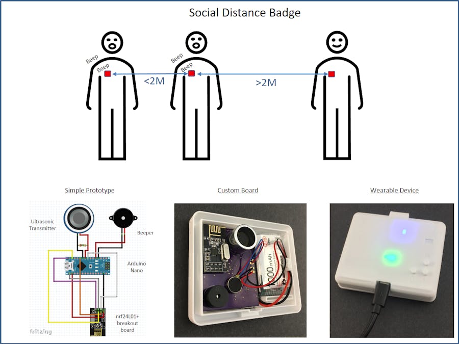
This project is meant to help people maintain social distance to avoid spreading COVID19. In some settings and surroundings its easy for people to forget to keep a safe distance, and so this device could help remind them. For example, for younger children this device makes it clear what is safe distance and what is not. In situations like public events where strangers need to maintain a distance the device can provide consistent guidance without people having to police themselves or each other. This could be useful in schools, museums, recreational facilities, or workplaces.
The device does not require wifi and needs only minimal infrastructure to charge the device (USB 5v). It uses basic technology and can be put together using low cost readily available components.
There are two designs for flexibility- a simple one that can be made with off the shelf boards and modules in a couple hours and another that uses a custom board for a full product.
How it WorksEveryone is given a device to wear. The devices measure the time it takes for a sound to travel from one person to another. Sound travels approximately 0.340 meters per millisecond, so for a social distance of 2 meters, sound takes approximately 6ms to travel that distance. We can use high frequency sound, so that it remains inaudible to people.
To make this measurement, we need to quickly and accurately synchronize between the devices, and that's where we use radio waves, traveling at the speed of light. We use an nrf24l01+ transceiver module to send a communication between the devices. This communication occurs very quickly (under 1 ms) so can be thought of as nearly instantaneous.
The communication has the following steps:
1. One device (the 'sender') sends an RF packet to all other devices in radio frequency range. It then begins listening for an ultrasonic ping.
2. Any device that receives the RF signal immediately responds with an ultrasonic ping.
3. The ping from the closest device to the 'sender' arrives first to the 'sender'. The 'sender' measures the duration between RF send and ultrasonic receive. If this duration is less than approximately 6ms, we know the users are too close, and the RF sender alerts its user via the piezo buzzer.
4. Each device becomes a 'sender' on random occasions in order to ensure the RF channel is shared and every user has distance measurements.
Video Showing the Devices in ActionHere is a short video about the device:
Design GoalsOne of the goals of the design was to minimize the component count and leverage the Arduino Nano as much as possible for the ultrasonic send and receive. For sending, two output pins are used in push-pull fashion, supplying 10v peak to peak output to the piezo ultrasonic transducer. A timer driven interrupt is used to generate the 40kHz ping signal. For receiving, the Arduino Nano's differential comparator inputs are used to detect zero crossing of the signal. The same timer driven interrupt implements a matched filter that detects the ping. It works surprisingly well at the distance ranges needed.
Unfortunately, an Arduino Nano draws significant current (30-40mA) all the time, in order to power the MCU and the USB to serial interface. This means an Arduino is great for prototyping but the finished device needs to use less power to keep it small and battery operated. The finished device also needs to be able to manage battery charging, allowing the power to be turned on and off, and have a compact build.
Two Versions of the ProjectFor this reason this project has two versions. There is a Simple Prototype, which allows you to easily and quickly build working devices to experiment and learn. The other version is called the CustomVersion, since it uses a custom board similar to the Nano, but with features to reduce power consumption, charge a battery, and power a vibrating motor, and in a smaller form factor. Both versions run the same Arduino code, and can be used together. The Simple Prototype is easy to build. The Custom Version is a more advanced project, and requires populating a PC board and programming the Arduino boot-loader.
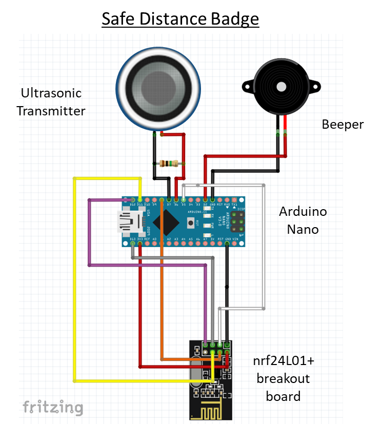
Building the Simple PrototypesYou will want to build at least two prototypes so that you can see how they work together. The prototypes can be wired using jumpers with Dupont connectors. Here is the schematic.
Ultrasonic Receiver/Transmitter
I started with using the piezo transducers removed from the HC-SR04 ultrasonic/sonar distance sensor module. The receiver transducer on these modules works very well for this application. The transmitter transducer also works with slightly less sensitivity. I experimented with other parts, like the Pui Audio UT-1640K-TT-2-T transmitter, but got poorer performance than the above.
A 1 mega-ohm resistor is placed across the transducer to help bias the comparator. The value is not super critical and it will work with a value from a few hundred K ohms to a few M ohms.
Beeper
The beeper should be a 5v continuous tone beeper that contains its own tone oscillator.
nRF24L01+ Breakout Board
These breakout boards are available from a variety of sources. Below is a table that shows the hookup. Make sure the connections are tight, since loose wires will cause the transmission to fail.
Upload the Firmware
Program the Nano with the Arduino IDE. The firmware depends on the RF24 library, which can be downloaded from the IDE's Tools->Manage Libraries... menu.
The easiest way to power the prototypes is to use cell phone portable charging battery packs. The 5v USB output can power the Nano. You can also use a single Lipo cell with built-in protection to power the Nano. Just supply the power directly to the 5V pin and GND.
Simple 3D Printed Case
For the Simple Prototype, there is a simple case design, making it possible to wear the device like a medallion.
the case can be printed out in PLA or PETG. I used.2mm layer height and 20% infill.
A shoelace can be used as a lanyard and strung through both halves to help hold them together. The halves can be pressed together.
Firmware Tweaks
The firmware has some parameters that you can play around with and change the behavior of the device. For example, the distance trip point can be adjusted, the sensitivity of the matched filter, the ultrasonic output frequency, and RF frequency and strength.
Custom VersionThe custom version relies on a custom designed board for this application. It uses a Atmega 328P processor at 16MHz, just like the Arduino Nano. This was my first standalone Arduino board and I used a couple tutorials on the Arduino site that showed how to construct them:
https://www.arduino.cc/en/Main/Standalone
https://www.arduino.cc/en/Tutorial/ArduinoToBreadboard
https://www.arduino.cc/en/Tutorial/ArduinoISP
The board's main differences include:
- Processor powered at 3.8V, to further reduce current consumption. This is the lowest specified voltage for reliable 16MHz operation.
- nRF24L01+ powered at 3.0v, to reduce current consumption.
- No USB to serial converter, to reduce current consumption. We will need an off-board USB-to-serial converter to program the board.
- A USB connector for charging and a single cell LiPo charge circuit to safely charge a 1000mAh cell. This will power the device for approx 40-50 hours.
- On and Off push-button circuit using voltage regulator enable pins.
- Another voltage regulator to drive the vibrating motor.
Below are the steps needed to complete the PCB for the custom version. This requires preparing a PC board with solder paste, placing the SMD components, and heating the boards. I assume some familiarity with these steps. If you need a refresher, check online. Here is a good one on skillet reflow soldering from Sparkfun.
1. Get the board made. I used OSH Park to have 3 boards created. Here is a link to the project on their site.
2. You can go to OSH Stencils and make an inexpensive stencil for applying the solder paste. Choose the 3 mil Polyimide film to put down a thin layer of paste. You will need to upload the attached eagle.brd file to order the stencil. You may want to purchase their acrylic jig set, if you do not have a way to hold the stencil and board in alignment.
3. Order the parts on the attached BOM. I ordered them from Mouser electronics.
4. I like to organize all my parts on double-stick tape, in order to minimize the chance or error when populating the boards.
6. Once you get the boards, clean them with acetone and make a jig to hold the board and stencil to allow you to spread the solder paste. You will want to make sure you have good alignment of the stencil with the board.
7. Apply the lead free solder paste. Below are the results of my solder spreading. I used 5 mil polyimide, rather than 3 mil, and ended up with too much paste in spots. I recommend the 3 mil for this project.
8. Place the components on the board. You can use a tweezers or a vacuum system. I use both, depending on the component size. For the vacuum system I use an old aquarium airpump, airhose, bic pen, paste needle, and heat shrink tubing on the needle.
9. Here we use a skillet that is no longer used for food prep. Carefully transfer the boards to your skillet. Heat the skillet and reflow the boards. I use an infrared thermometer to check the temperature as I visually check for solder melting. Pull the boards off and let them cool.
10. Inspect the solder for shorts and do some tests with an ohmmeter to make sure there are no shorts (check the point where the battery is connected, as one example). Make any fixes using solder wick.
Wait with soldering the through-hole parts until the bootloader is installedand tested. Installing the bootloader requires 5v power, and uses the same pins as the nRF24L01+ which could damage this part if its installed.
11. Solder only the J2 ICSP/Serial header to the board. Do not solder any other through-hole parts at this time
12. First power up - Use a 5v supply instead of a LiPo cell to initially power up the board. Use a 100 ohm resistor in series with the supply to limit the current to a low level. Monitor the current and make sure its only a few microamps. Press the 'on' button and check for proper voltage of the voltage regulators on C10 and C11. Press the 'off' button and the voltage should shut off. If this checks out you are ready to program.
Programming the Custom VersionThis board needs a bootloader installed for it to behave like a typical Arduino board. We will be programming the Arduino bootloader using the technique in the Arduino tutorial here, which requires using another Arduino as an ISP. To do this we first need to make the proper connections to the board. The board has a 2x5 pin header labelled ICSP/Serial that exposes all the pins required for programming the bootloader as well as Arduino program uploads.
You need to hack the Adafruit 10-pin 2x5 Socket-Socket 1.27mm IDC (SWD) Cable to make the connections. The picture below shows one approach - using a male pin header as a adapter to simplify the connections. Pin 1 is the GND pin and is the red wire in the ribbon cable.
When connecting the cable to the board, please ensure all the pins align appropriately. The pins are small and it can be hard to tell all 10 pins match up.
As shown on the Arduino Tutorial, you need to connect to the MOSI, MISO, SCK, RESET, GND, and power. Its OK to connect 5v to the pin marked 3.8v on the programming header since everything is 5 volt tolerant and we did not install the nRF24L01+ yet.
Once connected follow the tutorial on programming the bootloader. When programming the bootloader, select Arduino Nano as the board type for the bootloader image. This way the custom board will be recognized as a Nano by the Arduino IDE.
Arduino Programming
Now that the bootloader is programmed, you will want to test Arduino programming with a small program. Choose the blink program and if you like change the LED pin in the program to pin 4, so that the board LED will blink. In this step we want to go through the mechanics of programming and make sure we can land a program successfully on this board.
Since the custom board does not have an FTDI chip on it to translate USB to Serial communication, we need to attach the FTDI breakout board to program it. The Custom Board is like the Arduino Pro Mini, except it runs at 3.8V and 16MHz, rather than 3.3v and 8MHz. We will use the same wire hookup to program as the Pro Mini 3.3v, but in the IDE we will select Nano since we used the Nano bootloader.
The first step is to wire the FTDI breakout board with the Adafruit 10-pin 2x5 Socket-Socket 1.27mm IDC (SWD) Cable, to connect to the serial TX and RX ports, GND, and 3.3V. For this first programming we will want to power the board through the cable at 3.3v. We will be using the reset button on the board (S1) at the appropriate moment to allow programming.
Once the blink program loads successfully, the covid12.ino file can be uploaded to the board.
Subsequent programming can be done with battery power. In this case the positive power lead from the FTDI breakout board should be left disconnected. Don't forget to press the on button (S3) on the board to supply power. Also need to press the Reset button (S1) at the appropriate time to allow programming.
Solder remaining Through-hole Components
Once programming checks out you can solder the remaining through-hole components. You will need to cut the male pin header leads on the nRF24LS01+ so they do not protrude too far when soldered on the board. The Lipo cell wires can be soldered directly to the board or attached with a connector plug as shown.
3D printedEnclosure
The enclosure holds the board and battery and allows charging through the micro USB port, user control of the power buttons, and visibility of the LEDs indicating RF transmission/receive and charge state. A standard badge strap can be used to attach it to clothing. A lanyard can also be used.
The enclosure has 3 parts - the case front, case back, and 2 switch buttons.
Print in PETG using 0.2mm layer height, 20% infill. You will need support for the case back for the bar that attaches to the badge strap. The picture below shows where the support is needed.
The switch buttons press fit in the holes in the back case, from the inside of the case. They have a lip that holds them in place so they should not fall out.
The circuit board and Lipo cell fit side by side in the back case. the vibrating motor can be stuck on the PC board as shown.
Operation
Power on by pressing the on button momentarily. You will see the blue LED flashing dimly when sending an RF signal and flashing more brightly when it receives an RF signal from another unit. Power off by pressing the off button. When off, the devices only uses a few microamps of power. To charge the device, use any 5v USB power source. Charging takes approximately 4 hrs for a fully depleted cell. A red LED will indicate charging and a green LED indicates the charge is complete. The device should run 50 hrs on a charge.
Push Pull Output
We use a push-pull output to generate 10v peak to peak pulses from a 5v source in the Simple Prototype, and the Custom version generates a 7.6v peak to peak pulse from a 3.8v source. This is done using 2 output pins that alternatively swing in opposite directions. This way we can drive the ultrasonic transducer with a stronger signal.
Since we use the same 2 pins as analog inputs, we need to ensure the signals on the pins settle down to microvolt levels quickly in order to measure any received ping. This is done by first setting both pins low, so that the voltage across the ultrasonic transducer is reduced. Then each pin is set as an input, and allowed some settling time as well.
Matched Filter
Matched filtering is a common way to detect return echos in radar and sonar systems. The matched filter is the optimallinear filter for maximizing the signal-to-noise ratio in the presence of additive random noise. It works by measuring the correlation between the incoming signal and a template signal (the ping). A high correlation means the signals match.
At each time point the correlation (sum of products) is calculated between the match filter waveform and the input waveform. For example, the sum below calculates the first cross correlation point.
As new input data comes in, the data is shifted, and a new correlation point is calculated.
The closer the match between the waveforms, the higher the (positive or negative) magnitude of the correlation. If the signals are out of phase, the correlation is negative. By taking the absolute value and using a threshold we can detect the ping in the presence of noise.
The longer the ping, the larger the match filter, and the more sensitive the detection becomes. The example above shows a period of 5, but the firmware uses a ping of 2 miliseconds, which corresponds to 80 periods of the 40kHz square wave.
In general this type of signal processing usually requires more processing power than an 8-bit Arduino and is done in the frequency domain using the Fast Fourier Transform (FFT). However, in this case we take advantage of a a few aspects of this problem to pull it off in the time domain on an 8 bit processor. First, we are dealing with a 1 bit input signal from the Arduino's input comparator. Also, our ping signal has a repeating pattern since it has a constant frequency. Finally we are sampling the signal right at the Nyquist frequency (80kHz) for the 40kHz ping. This simplifies the math and the memory requirements for the processing.
In the firmware interrupt, the matched filter calculation is done using a circular buffer the size of the match filter (ping length). This allows us to efficiently keep track of the start and end samples.


_3u05Tpwasz.png?auto=compress%2Cformat&w=40&h=40&fit=fillmax&bg=fff&dpr=2)


Comments