


Hardware components | ||||||
| × | 2 | ||||
| × | 4 | ||||
| × | 1 | ||||
Software apps and online services | ||||||
| ||||||
Hand tools and fabrication machines | ||||||
 |
| |||||
| ||||||
This project was inspired on the terrible wildifires that destroyed a big part of my country, Spain, during the summer of 2025. Many areas did not had proper mobile phone coverage and some base stations were affected by fire.
Meshtastic communication can be a great way to coordinate emergency response, by means of sending data acquired through sensors, as well as critical messages for a fast intervention, such as anemometer, weather vane, pressure, temperature, etc.
SolutionDual Wio Tracker L1 Portable Solar Station has four solar panels that can be oriented in order to keep two 906090 6000mah lipo batteries fully charged. It can also charge two Wio Tracker L1 nodes, connected to the Station by magnetic pogo connectors. This also allows Grove sensors to be connected to the Station if needed and transmit valuable data to other locations.
When I started thinking about the solution some requirements came to mind. First, the Station had to be modular, made out of individual parts. This allows the solution to be escalated depending on needs, and also be build up from separate components. Second requirement was to have a roughed, ip65 construction that could resist bad weather conditions. Using modularity means that, in case water damages one module, it will not affect the rest of the modules. It also had to be as lightweight as possible, offer some redundancy operation so it is actually two devices in one just in case half of the equipment is damaged.
The general design of the project has been done using Shapr3D on an iPad Pro.
Some parts, like the 3 water resistant boxes were created with the amazing parametric model of pb-tec in Printables using Openscad. One problem I found is that only STL format of Openscad seems to be importable from Shapr3D, which required some good thinking to find a solution.
All pieces should be printed in a material suitable for resisting sun radiation and weather conditions. ABS, Nylon-CF, ….. As the design is modular, 3D printers with a 256 cubic millimeters volume can print the needed parts with the exception of the Base and the Panel Boards that have to be printed in parts. I have included the .3mf file for importing it into Bambu Studio or Orca Slicer.
The main core of the Dual Wio Tracker L1 Portable Solar Station (I will call it Station from now on) are three core ip65 boxes that are communicated by some sealed holes to assure water resistance. These are named: Top Box, A Box, and B box.
Top box. This piece works as an interface to the Wio Tracker L1 devices, offers plenty of space for internal sensors connected by Grove port, and is the entry point of the electricity coming from the solar panels towards A and B boxes. On top of it is the Top Support that holds the hinges to support the two boards with the solar panels.
A Box. This is the box that provides functionality to the front solar panels, including the batteries and electronics for charging them. (Front solar panels are the ones that are closer to the openings of the core boxes).
B Box. This is the box that provides functionality to the rear solar panels, including the batteries and electronics for charging them.
The three boxes should be interconnected and glued together, sealing them to assure water resistance. Silicone sealing cord can help on this, as well as hot glue and 3m double side tape.
Around the main core of the Station are several pieces which were designed and 3D printed. We will call them Outer pieces. These are: Top support, Base, Corners, and Wio Tracker Interfaces.
Around the main core of the Station are several pieces which were designed and 3D printed. We will call them Outer pieces. These are: Top support, Base, Corners, and Wio Tracker Interfaces.
All parts are either glued to the core of the unit, temporary fixed with double side tape or secured via a heavy duty Nylon strap. This nylon strap is 2.5cm wide and 1mm thick and is similar to the ones used in backpacks. This band goes through the Outer pieces, allowing the Station to be carried as a bag and also securing it in place to a post, vehicle roof, etc.
Top support. This piece supports the two boards that hold the solar panels. It has some circular hinges that allow the boards to orient to the sun.
It also has an opening on its lower side that allows a high resistance nylon band to go through it, as well as some circular windows to install the This piece needs to be glued to the Top Box. Tongue part goes to the back side of the unit.
Base. This part is the support of the whole Station and is right below A Box and B Box. It has some interesting functionality, several cylinders in the lower part that hold some metallic discs (more on this later). As mentioned above, the base has some openings to allow the strap to attach to it.
Corners. This two pieces serve as a guide for the strap. These could be printed in TPU to work as bumpers or printed in the recommended materials. These have to be glued to Box A and Box B.
Wio Tracker interfaces. These two pieces hold the two Wio Trackers while they are charging. Each interface has a dock to vertically drop the Wio Trackers and a pogo pin magnetic connector with 6 pins. One of the most critical parts during the design was how the Wio L1 Trackers would connect to the dock using magnetic 6 pins pogo pin connector. For this reason I have modified the case of the Wio L1 Tracker provided by Seeed Studio to make it 2 cm taller.
The pogo pin makes contact with the Wio Tracker and provides charging plus access to grove sensors connected to the Station.
Wio Tracker interfaces also have a grove to pass the nylon strap through it. Each one of the Wio Tracker interfaces have to be Glued to the core of the Station as shown in the image.
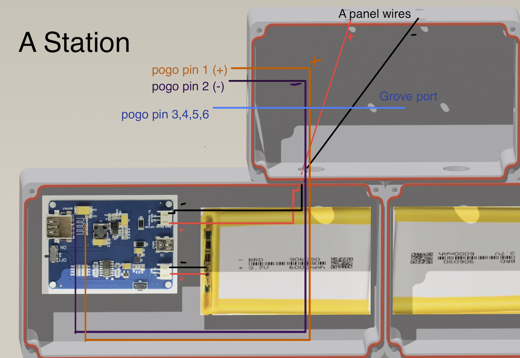
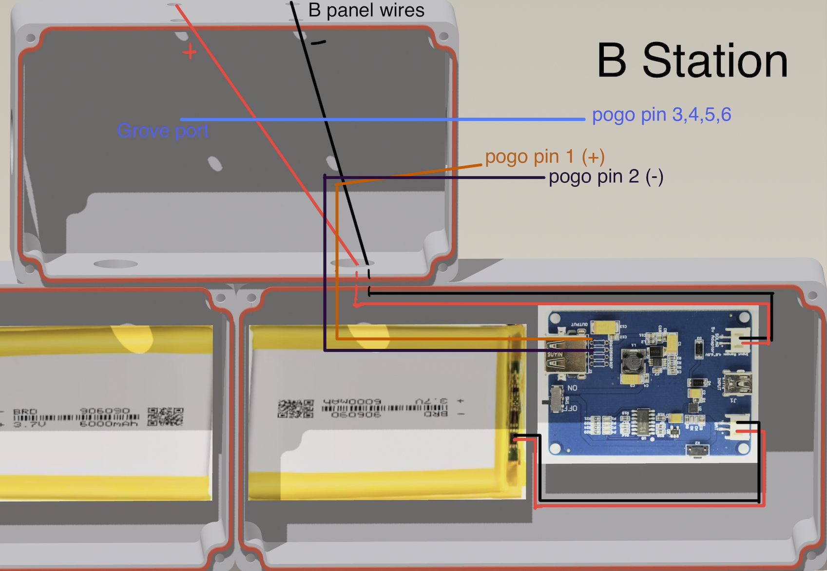
Connections can be seen in the previous image. 6 pins are needed, 2 for the solar connector and 4 for the Grove port.
There is enough space for the JST 2mm connector that goes into the solar connector of the Wio L1 Tracker, as well as for the grove connector, pogo pin connector and cables. The two wires of the solar charge go into pins 1 and 2 of the pogo pin, and cables from the grove connector go into pins 3, 4, 5, 6.
Magnets of the pogo pin are surprisingly strong which is an added benefit to keep the Wio L1 Tracker devices in place.
The interfaces need to be printed in two parts and glue together, some plastic unions are handy to keep the parts in place. The interfaces have a grove to conduct the cables to Top Box. Once the pogo pin is installed the interfaces can be glued to the core part.
ElectronicsThe Station is actually two stations-in-one, Station A and Station B, which means that if one of them stops working the other will still work. This redundancy is paramount for emergency services.
Both stations are equal so lets focus on Station A. Station A is made up of A panel and A Box. I am considering to use the same panels mounted in SenseCAP Solar Node P1/P1 Pro for Meshtastic, since I am really happy with the performance of the panel to keep the batteries of the unit never dropping below 90 percent in my place (Casla, Segovia). I opened a ticket to Seeed Studio support to know the actual dimensions of the panels but they could not provide me this information, so I am assuming the dimensions of each panel are 180x180mm. There are commercial solar panels of 90x90mm that could also be used.
The two panels are connected in parallel to increase the intensity and keep the current voltage provided by each panel. This will assure a faster charging of the batteries. The cables are connected to the hinge screws that hold the board to the Top support piece. I think this solution will work well and also will minimize the possibility of entering water to the Station. lexman connectors are needed in order to transmit the energy to the screws.
Cables from solar panels in the front panel pass through Top Box and go to Box A. (same for rear panel and Box B). These are connected to two Lipo Rider Pro, one on Station A and another for Station B. From there a 906090 6000mah lipo battery will store the energy provided by the solar panels for Station A (another battery for Station B).
Full connection schematics below:
When we have all the printed parts and electronics it is time to mount everything. Basically is to glue together the core ip65 boxes (please do this part with the covers removed), paying attention to the orientation and the holes that will connect each part.
Once we have the core completed, lets move on to the base. You have to glue together the two pieces that form the rail where the core will rest. After that install the steel disks on the openings of the base. This will keep the magnets of the legs in place during transportation.
It is recommended to use some removable double side tape once all the electronics are in place and the core boxes closed to secure the base to the core.
Legs are straightforward to mount, you need a 8 neodimium magnets 20 x 3 x 5 mm plus the CSK screws m4 20mm plus nuts and washers, as well as the metal legs and the TPU printed parts.
Connect the solar panels in parallel for each side (A, B) and use a lexman connector to tie them together. Use a couple of nuts and the hand knob screw to secure the lexman connector to sides 1 and 2 of the panel. The screw will transmit the energy to the lexman connectors you are going to use on the Top Support. hand knob screw will also be used to fasten or loose the panels for inclination.
Once we have the charging cables, pass them through the openings in Top Box and take the ones belonging to front panel to A Box and the ones belonging to rear panel to B Box. Remember, front panel is the one closer to the covers of the core boxes. Pay special attention to polarity.
Pogo pin cables from A interface must be routed through the grove of the Wio Interfaces and passed through the circular window to Top Box. From there energy cables will travel to Box A (identically for B interface to Box B). The rest of the cables go to a grove connector that will allow to connect sensors and have the information they get transmitted by the Wio Trackers.
OperationOperation is really simple and almost self explanatory. Make sure the Station is stable, using either the legs included in the base or the strap to secure the unit to a post or hang it as needed. Legs can be mounted so the TPU feet are in contact with the floor, or the magnets are in contact with a metallic surface.
The base includes some steel disks so the leg neodymium magnets will be secured to the unit during transportation.
The nylon strap can be used for holding the Station secure against a pole, tree branch, wall, wire fence, etc. So basically this Station can be used in multiple scenarios.
Remove the Wio Trackers if they are placed in the unit and extend the solar panels and orient them to get the best possible energy conversion from the sun. There are very handy phone applications for Android and IOS that will provide the best possible orientation for the panels.
If charging of one or both trackers are needed, please put them in the docks. If internal sensors are required for the operation, remove the screws of Top box and connect the sensor to the grove port.
For the electronics I decided to use comercial parts like two Lipo Rider Pro boards from Seeed Studio to assure a flawless operation. These boards allow the charging of the batteries via usb, handy for having the batteries fully loaded before using the Station in the wild. They also have USB out, so charging of other devices like torchlights or mobile phones is possible.Other Battery Management Systems (BMS) could have been used, but generally these parts do not allow charging of external devices which is one of the requirements for the Solar unit.
I intentionally decided not to expose usb in or out connections for the Lipo Rider Pro to the outside. This would increase the possibilities of entering water into the unit. In order to use those ports, it is better to unscrew the lid of side A or B and use the USB ports.
One of the possible improvements is to use eight solar panels, four on each panel, instead of two. The additional solar panels could be folded with a vertical hinge on each side of the panels. This could increase the charging speed as well as protect the panels when folded, assuring a better protection when transporting the Station.
This project has been extremely fun to work on, so I would like to thank Seeed Studio and Hackster.io for organizing it. Due to the short time to present the solution for the Challenge it was not possible to validate the proof-of-concept and build it. Also some parts like the Lipo Rider Pro are backordered. Many functional and non-functional decisions that need to be validated were taken in order to create this project and I did my best to make sure they will work at first try.
I have prepared for printing all the 3D parts in a Bambu Studio file. This file can also be imported in Orca Slicer.
TPU filament
ASA filament
ASA-CF reinforced filament for legs (or aluminum legs)
3m double side tape FIXCHORD 3M VHB
8 Steel disks 20 mm diameter x 2.5 mm thick (base)
8 neodimium magnets 20 x 3 x 5 mm (base)
CSK screws m4 20mm plus nuts and washers
3 meters nylon heavy duty 25mm width belt
12 m2 screws and m2 Insert nuts for core boxes
round Lexman connectors (m4 internal diameter)
4 hand knob screws m4 50mm plus nuts
Cable that supports 3A
4 magnetic 6 pins pogo pins Male Female Ear Wire
4 grove connectors
2 two pin JST 2mm connectors (for solar connection on the Wio Tracker L1)
Hot glue gun
2 lipo batteries 906090 6000mah
2 Lipo Rider Pro boards from Seeed Studio
4 180 x 180 5w solar panels
2 batteries Lipo 103450 2000mAh or better for the Wio Tracker L1
_______________________________________________________________
Initial project that was selected is presented below:Dual Wio Tracker L1 Portable Solar Station has four solar panels that can be oriented in order to keep two arrays of 18650 batteries fully charged. It also holds two Wio Tracker L1 nodes, connected to the station by magnetic pogo connectors, that also allows Grove sensors to be connected to the Station if needed.
Station also holds some usb-c and usb 3.0 plugs to charge other devices, such as mobile phones or flashlights.
Grove port allows users to quickly add sensors to the nodes, by means of a dedicated connector on each side of the unit. Devices like anemometer, weather vane, temperature or atmospheric pressure sensors, for instance, can be plugged in and be operative in seconds.
Wio Tracker L1 case includes a pogo pin connector that exposes both grove port in the unit and charging connectivity. This can be also used for battery extension by means of a battery connection through the pogo pin, as well as small sensors like temperature or air quality
Station is lightweight, uses carbon fiber and military grade aluminum for both being lightweight and sturdy. Nodes can be easily and quickly removed from the station for quick operation, or they can be used connected to the station.
It is painted in vivid red color to be easily found. It also counts with IP65 covers for AC connection and have the batteries ready even before starting the adventure. Some basic led indicators inform about battery charge.
Although this was inspired for emergency response, this station is ideal for camping, trekking, 4x4 routes, paragliding, biking, mountain climbing and any other adventures.


Comments